


MM3156A DRUM SANDER
5
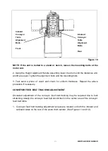
completely understood or if in doubt as to whether the tool or outlet is properly grounded.
5. Use only 3-wire extension cords that have grouding plugs, and the receptacles must accept the
tool’s plug.
6. Have a damaged or worn cord repaired or replaced immediately by a qulified technician.
EXTENSION CORDS
When using a power tool at a considerable distace distance from a power source,use an extension
cord heavy enough to carry the curremt that the tool will draw. An undersized extension cord will
cause a drop in line coltage,resulting in a loss of power and ocerheating.
When working with the tool outdoors, use an extension cord that is designed for outdoors.
Before using an extension cord,inspect it for loose or exposed wires and cut or worn insulation
Also, do not use an extension cord on a take up reel. The electric current passing through the
extension cord will generate heat, and if the cord is wrapped around a reel, a heat buildup will result
that could melt the insulation, causing a fire and/or electric shock.
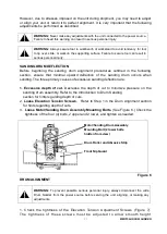
CAUTION:
Keep the cord away from the sanding area and position the cord so that it
will not be caught on lumber, tools, or other objects during sanding.
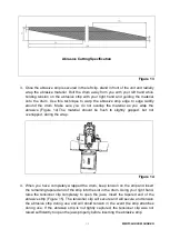
INTRODUCTION TO DRUM SANDING
FUNCTION
Drum sanding, sometimes referred to as
”abrasive planting” is a repetitive process of
sanding both sides of wooden stock to a desired thickness and/or smoothness. When
this performed correctly, both face surfaces will be parallel to one another.
Do not confuse drum sanding with thickness planning!
Drum sanding gradually
removes material in increments of 1/32” or less depending on sanding grit, stock
hardness, stock hardness, stock width, etc. Thickness planning,on the other hand, is for
quick,
bulk material removal at rates up to 1/8” per pass with portable machines. If you
have used a thickness planer to smooth and dimension stock you will quickly learn to
work
with
your new drum sander and not against the machine.Be patient, let the drum
sander do the work,1/32”or less per pass for best results.
The most common mistake made
with a drum sander is forcing it to remove too much
material too fast. Variables such as sandpaper grit, stock width, wood type, feed rate,
and moisture content all influence how much material can be removed in a single pass.


