IX System Piping
A. General System Piping Precautions
Warning
insTall bOilEr sO THaT THE gas igniTiOn sYsTEM COMPOnEnTs arE PrOTECTED
FrOM WaTEr (DriPPing, sPraYing, rain, ETC) During aPPlianCE OPEraTiOn anD
sErViCE (CirCulaTOr rEPlaCEMEnT, ETC).
CauTiOn
THE HEaT EXCHangEr usED in THE FCM is MaDE FrOM a sPECial aluMinuM allOY.
FailurE TO TaKE THE FOllOWing PrECauTiOns COulD rEsulT in sEVErE bOilEr
DaMagE.
•
bEFOrE COnnECTing bOilEr, MaKE surE THaT THE sYsTEM is FrEE OF sEDi-
MEnT, FluX anD anY rEsiDual bOilEr WaTEr aDDiTiVEs. FlusH THE sYsTEM iF
nECEssarY TO EnsurE THaT THEsE COnTaMinaTEs arE rEMOVED.
•
DO nOT COnnECT THis bOilEr TO a sYsTEM THaT is subJECT TO rEgular aDDi-
TiOns OF MaKEuP WaTEr Or OnE WHiCH EMPlOYs raDianT Tubing WiTHOuT an
OXYgEn barriEr.
•
DO nOT aDD anTiFrEEZE Or OTHEr bOilEr WaTEr TrEaTMEnT CHEMiCals
EXCEPT THOsE lisTED in ParT Xi OF THis Manual.
•
MainTain THE PrEssurE in THE bOilEr aT a MiniMuM OF 12 Psi.
•
DEsign sYsTEM TO EnsurE THaT THE FlOW Falls WiTHin THE liMiTs CallED
FOr in TablE 9.1.
B. System Design
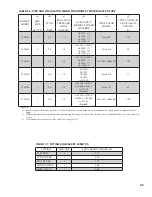
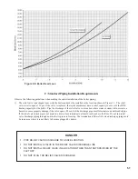
Proper operation of the FCM boiler requires that the water flow through the boiler remain within the limits shown in Table
9.1 any time the burner is firing. Failure to maintain the flow within these limits could result in erratic operation or premature
boiler failure.
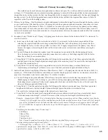
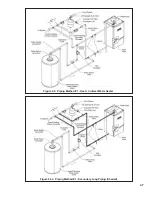
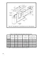
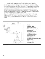
There are two basic methods that can be used to pipe the FCM boiler. Method #1 is almost always preferred. The
instructions on the following pages describe these methods for piping FCM boilers and explain how to size the circulator and
piping. Additional information on hydronic system design may be found in Installation of Residential Hydronic Systems (Pub.
#200) published by the Hydronics Institute in Berkeley Heights, NJ.
TablE 9.1: FlOW rEQuirEMEnTs THrOugH bOilEr
BOILER MODEL
MIN. REQUIRED FLOW
(GPM)
MAX. ALLOWABLE
FLOW (GPM)
FCM070
4.0
9.0
FCM090
4.0
9.0
FCM120
4.5
12.0
Summary of Contents for FREEDOM
Page 8: ...8 Figure 1 Wall Mounting Hole locations ...
Page 9: ...9 Figure 5 2 Boiler Mounting Hardware ...
Page 11: ...11 Figure 6 1 Boiler Installed In A Confined Space Ventilation Air From Inside ...
Page 42: ...42 FIGURE 7 51 CONDENSATE PIPING ARRANGEMENT ...
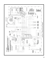
Page 55: ...55 Figure 10 1 Wiring Connections Diagram ...
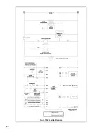
Page 56: ...56 Figure 10 2 Ladder Diagram ...
Page 57: ...57 Figure 10 3 Wiring of Isolation Relay for Control of Two Heating Circulators ...
Page 60: ...60 FCM Series Lighting and Operating Instructions ...
Page 66: ...66 FIGURE 12 2 BASIC MENU TREE ...
Page 75: ...75 ...
Page 77: ...77 ...
Page 79: ...79 ...
Page 80: ...80 ...
Page 81: ...81 ...
Page 83: ...83 150 151 152 153 154 155 ...
Page 84: ...84 156 157 158 159 160 161 ...
Page 85: ...85 162 ...


