3
I Product Description
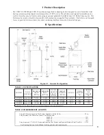
The FCM070, FCM090 and FCM120 are aluminum gas fi red condensing boilers designed for use in forced hot water
heating systems requiring supply water temperatures of 180°F or less. These boilers are designed for installation on a
wall, however they may be fl oor mounted using an optional pedestal kit available from U.S. Boiler Company, Inc. This
boiler may be vented vertically or horizontally with combustion air supplied from outdoors. This boiler is not designed
for use in gravity hot water systems or systems containing signifi cant amounts of dissolved oxygen.
II Specifi cations
MODEL*
NO. OF
SECTIONS
MAXIMUM
INPUT
(BTU/hr)
MINIMUM
INPUT
(BTU/hr)
D.O.E.
HEATING
CAPACITY
(BTU/hr)
IBR NET
RATING
(BTU/hr)
AFUE (%)
WATER
VOLUME
(Gal.)
APPROX.
NET
WEIGHT
(lb)
FCM070
mono block
70,000
30,000
63,000
55,000
95.4
0.41
102
FCM090
mono block
90,000
30,000
80,000
70,000
94.5
0.41
102
FCM120
mono block
120,000
40,000
107,000
93,000
95.2
0.62
110
* Add suffi x “N” for natural gas and “P” for propane. Ratings are the same for both fuels.
Using 60/100mm Concentric Vent System Supplied with the Boiler................................................................25 in.
Using Optional 60/100mm Concentric Vent Components:
FCM070
....................................................................................... 32 ft
FCM090
....................................................................................... 32 ft
FCM120
....................................................................................... 18 ft
Using Approved 3” AL29-4C Horizontal Stainless Vent System and Optional Stainless Steel Vent Kit..........55 ft
See Venting Section for additional venting options and requirements
TablE 2.3: MaXiMuM VEnT lEngTHs
TablE 2.2: sPECiFiCaTiOns
Figure 2.1: General Confi guration
Summary of Contents for FREEDOM
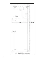
Page 8: ...8 Figure 1 Wall Mounting Hole locations ...
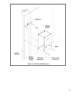
Page 9: ...9 Figure 5 2 Boiler Mounting Hardware ...
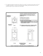
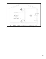
Page 11: ...11 Figure 6 1 Boiler Installed In A Confined Space Ventilation Air From Inside ...
Page 42: ...42 FIGURE 7 51 CONDENSATE PIPING ARRANGEMENT ...
Page 55: ...55 Figure 10 1 Wiring Connections Diagram ...
Page 56: ...56 Figure 10 2 Ladder Diagram ...
Page 57: ...57 Figure 10 3 Wiring of Isolation Relay for Control of Two Heating Circulators ...
Page 60: ...60 FCM Series Lighting and Operating Instructions ...
Page 66: ...66 FIGURE 12 2 BASIC MENU TREE ...
Page 75: ...75 ...
Page 77: ...77 ...
Page 79: ...79 ...
Page 80: ...80 ...
Page 81: ...81 ...
Page 83: ...83 150 151 152 153 154 155 ...
Page 84: ...84 156 157 158 159 160 161 ...
Page 85: ...85 162 ...


