background image

37

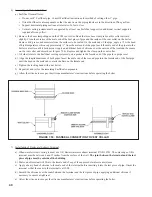
3)  Assembly of Metal-Fab Corr/Guard Vent System:

a)  Corr/Guard General Notes:

•  Do not cut Corr/Guard vent components.
•  Refer to Corr/Guard installation instructions for proper methods of support.
•  Orient Corr/Guard components so that the males ends of all fittings point in the direction of the boiler.

b)  Start assembly of the vent system at the boiler. Remove the hose clamp shipped on the FCM vent collar. Bend the three 

hose clamp tabs on this collar outward slightly.

c)  Clean the exterior of the male end of the first piece of pipe and the inside of the vent collar on the boiler. Remove dirt, 

grease, and moisture from the surfaces to be sealed.  Dry surfaces or allow to dry thoroughly.

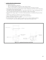
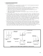
d)  On the male end of the pipe, apply a ¼” wide bead of silicone approximately ½” from the end of the pipe (see Figure 

7.47).

e)  Insert the male end of the pipe into the boiler vent collar until it bottoms out.
f)   Apply an additional bead of silicone over the outside of the joint and smooth out. 
g)  Replace and tighten the clamp on the vent collar.
h)  Assemble remaining Corr/Guard components in accordance with the Corr/Guard installation instructions. 
i)   Allow the silicone to cure per the silicone manufacturer’s instructions before operating the boiler. 

Figure 7.7:  Corr/guard Connection to Vent Collar

Summary of Contents for FREEDOM

Page 1: ...I O B R E T A W T O H D E R I F S A G Warning Improper installation adjustment alteration service or maintenance can cause property damage injury or loss of life For assistance or additional information consult a qualified installer service agency or the gas supplier This boiler requires a special venting system Read these instructions carefully before installing 101008 01R2 7 07 ...

Page 2: ...ler 80 125mm Concentric Venting 27 E Assembly of Stainless Steel Venting 36 F Condensate Trap and Drain 41 VIII Gas Piping 43 IX System Piping 44 A General System Piping Precautions 44 B System Design 44 C Standard Piping Installation Requirements 51 D Piping For Special Situations 52 X Wiring 54 XI Start up and Checkout 58 XII Operation 64 XIII Service and Maintenance 69 XIV Troubleshooting 71 XV...

Page 3: ... MAXIMUM INPUT BTU hr MINIMUM INPUT BTU hr D O E HEATING CAPACITY BTU hr IBR NET RATING BTU hr AFUE WATER VOLUME Gal APPROX NET WEIGHT lb FCM070 mono block 70 000 30 000 63 000 55 000 95 4 0 41 102 FCM090 mono block 90 000 30 000 80 000 70 000 94 5 0 41 102 FCM120 mono block 120 000 40 000 107 000 93 000 95 2 0 62 110 Add suffix N for natural gas and P for propane Ratings are the same for both fue...

Page 4: ...s boiler sizing guidelines For systems including a Alliance indirect water heater size the boiler to have either the DOE Heating Capacity required for the Alliance or the net rating required for the heating system whichever results in the larger boiler For systems that incorporate other indirect water heaters refer to the indirect water heater manufacturer s instructions for boiler output requirem...

Page 5: ...r combustion and away from areas that will contaminate combustion air Avoid areas near chemical products containing chlorine chloride based salts chloro fluorocarbons paint removers cleaning solvents and detergents Figure 4 1 Clearances To Combustible Or Non combustible Material ...

Page 6: ...T FAB SAF T VENT PROTECH FASNSEAL Z FLEX Z VENT III METAL FAB CORR GUARD VERTICAL OR HORIZONTAL AT LEAST ONE SIDE OPEN COMBUSTIBLE MATERIAL ON A MAXIMUM OF THREE SIDES 1 HEAT FAB SAF T VENT PROTECH FASNSEAL Z FLEX Z VENT III METAL FAB CORR GUARD HORIZONTAL OR VERTICAL WITH OFFSETS ENCLOSED ON ALL FOUR SIDES 2 1 2 HEAT FAB SAF T VENT PROTECH FASNSEAL Z FLEX Z VENT III METAL FAB CORR GUARD VERTICAL ...

Page 7: ...at wall selected does not have any framing or other construction that will interfere with the vent pipe penetration 5 Once a suitable location has been selected for the boiler and any needed modifications have been made to the wall use Figure 5 1 to locate holes A and B Make sure that the horizontal centerline of these holes is level Holes C and D may also be drilled at this time or after the boil...

Page 8: ...8 Figure 1 Wall Mounting Hole locations ...

Page 9: ...9 Figure 5 2 Boiler Mounting Hardware ...

Page 10: ...s a confined space Example A FCM120 and a water heater are to be installed in a room measuring 6 ft 3 in x 7 ft with an 8 ft ceiling The water heater has an input of 30000 BTU hr Total input in thousands of BTU hr 120000 BTU hr 30000 BTU hr 1000 150 MBTU hr Volume of room 6 25 ft x 7 ft x 8 ft 350 ft3 350 150 2 33 Since 2 33 is less than 50 the boiler room is a confined space Step 2a If the boiler...

Page 11: ...11 Figure 6 1 Boiler Installed In A Confined Space Ventilation Air From Inside ...

Page 12: ...f 25 Figure 2 1 For longer runs additional straight lengths and elbows are available from U S Boiler In some cases larger diameter concentric pipe must be used Each U S Boiler concentric vent component consists of an inner pipe of polypropylene and the outer pipe of steel Integral gaskets on each concentric fitting provide a gas tight seal A list of all U S Boiler concentric vent components is sho...

Page 13: ...00mm concentric vent terminal is supplied with the boiler as part of the standard vent system Vent Option 2 The exhaust terminal is U S Boiler part 8110701 The air intake fitting is a 90 degree elbow with a rodent screen supplied by the installer This elbow is made out of the same material as the rest of the air inlet system either galvanized or PVC and is installed as shown in Figure 7 3 Vent Opt...

Page 14: ...IN TABLE 7 5 U S Boiler 80 125mm VENT COMPONENTS SHOWN IN TABLE 7 4b AIR INTAKE MATERIAL GALVANIZED OR PVC Note 1 In Vent Option 1 the 80 125mm concentric straight section P N 101162 01 shown in Table 7 4a may be used between the boiler and the first 80 125 x 60 100 reducing elbow If this is done the overall maximum vent length is still restricted to that shown for Vent Option 1 in Table 7 1 above...

Page 15: ...15 Figure 7 2 Horizontal Concentric Venting Vent Options 1 3 Figure 7 3 Horizontal Twin Pipe Venting Vent Option 2 ...

Page 16: ...ON SIZE USED ON VENT OPTION COMMENTS 101490 01 90 DEGREE EL STANDARD 80 125mm 3 6 101542 01 90 DEGREE EL SWEEP 80 125mm 3 6 101491 01 45 DEGREE EL 80 125mm 3 6 101163 01 19 1 2 STRAIGHT 80 125mm 3 6 CAN BE CUT 101162 01 39 STRAIGHT 80 125mm 3 6 CAN BE CUT 101488 01 39 STRAIGHT 80 125mm 3 6 MAY NOT BE CUT 101161 01 78 STRAIGHT 80 125mm 3 6 MAY NOT BE CUT 101489 01 TELESCOPING STRAIGHT 80 125mm 3 6 ...

Page 17: ...wo 90 degree elbows with a rodent screen as shown in Figure 7 10 Vent Option 6 Use U S Boiler part 101495 01 with the appropriate flashing see Table 7 4b 7 Vertical Vent Terminal Locations Vent Options 5 6 Observe the following limitations on the location of all vertical vent terminals see Figures 7 10 and 7 11 The top of the vent pipe must be at least 2 feet above any object located within 10 fee...

Page 18: ... Figure 7 6a Location of Vent Terminal Relative to Windows Doors Grade Figure 7 6b Location of Vent Terminal Relative to Meters and Forced Air Inlets Figure 7 6c Positioning Vent Terminal Under Overhangs ...

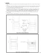
Page 19: ...Supporting Pipe Vertical and horizontal sections of pipe must be properly supported Support U S Boiler concentric venting near the female end of each straight section of pipe Exception Vertical runs of concentric pipe in an unused chimney Figure 7 36 need only be supported at the terminal and at the base of the run Support stainless steel venting as called for by the vent manufacturer s instructio...

Page 20: ...ATION THROUGH STRUCTURE ROOF ROOF AIR INTAKE PIPE STRUCTURE THROUGH STRUCTURE ROOF ROOF VENT PIPE SIZE 3 80 125mm CONCENTRIC AIR INTAKE PIPE SIZE 3 MAXIMUM LENGTH VENT FCM070 49 5 ft 49 5 ft FCM090 49 5 ft 49 5 ft FCM120 49 5 ft 49 5 ft INLET FCM070 49 5 ft 49 5 ft FCM090 49 5 ft 49 5 ft FCM120 49 5 ft 49 5 ft MINIMUM LENGTH VENT FCM070 2 ft 2 ft FCM090 2 ft 2 ft FCM120 2 ft 2 ft INLET FCM070 2 ft...

Page 21: ...21 Figure 7 10 Vertical Twin Pipe Vent System Vent Option 5 Figure 7 11 Vertical Concentric Vent System Vent Option 6 ...

Page 22: ...r spaces of the building Turn on clothes dryers and any appliance not connected to the common venting system Turn on any exhaust fans such as range hoods and bathroom exhausts so they will operate at maximum speed Do not operate a summer exhaust fan Close fireplace dampers d Place in operation the appliance being inspected Follow the lighting instructions Adjust thermostat so the appliance will op...

Page 23: ...e tooth hacksaw or a PVC saw to cut the plastic pipe and be careful to cut the pipe square De burr the cut edge of the plastic pipe with a file razor blade or fine sandpaper f Reinstall the inner pipe in the terminal section Slip the outside wall grommet over the terminal section and position so that it covers the joint between the outer pipe and the terminal Figure 7 24 g Make a mark on the termi...

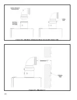
Page 24: ...24 Figure 7 20 Installation of Reducing Elbow on Concentric Boiler Collar Figure 7 21 Dimension L ...

Page 25: ...king the desired length of the outer pipe remove the plastic inner pipe by pulling it out from the female end b Cut the outer pipe only at the point marked in Step b using aviation shears a hacksaw or an abrasive wheel cutter Be careful to cut the pipe square De burr the cut end with a file or emory cloth c Cut the plastic inner pipe so that it will protrude 3 8 beyond the outer pipe when reinstal...

Page 26: ...26 Figure 7 24 Preparing 60 100mm Terminal Section for Installation in the Wall Figure 7 25 Attaching 60 100mm Terminal Section ...

Page 27: ...r are not used in 80 125mm vent systems The components listed in Table 7 4b are required for 80 125mm installations are not supplied with the boiler Before starting assembly of an 80 125mm vent system make sure that the planned installation is in accordance with the Vent System Design section of this manual and that all required 80 125mm vent components are on hand These components are available t...

Page 28: ...t marked in Step a using aviation shears a hacksaw or an abrasive wheel cutter Be careful to cut the pipe square De burr the cut end with a file or emery cloth d Make an insertion mark 1 from the male end of the outer pipe e Cut the plastic inner pipe so that it will protrude 3 8 beyond the male end of the outer pipe when reinstalled in the outer pipe Use a fine tooth hacksaw or a PVC saw to cut t...

Page 29: ...ure 7 32b c The male end of cuttable fittings must be held to the collar with three 10 x 1 2 sheet metal screws Drill a 1 8 hole through both outer pipes to start this screw Use a drill stop or other means to ensure that the drill bit does not penetrate more than 3 8 into the outer pipe Do not use a sheet metal screw longer than 1 2 Figure 7 32a d Use locking bands provided with all fittings to se...

Page 30: ... plastic pipe and be careful to cut the pipe square if necessary the plastic pipe can be removed from the terminal again for cutting De burr the cut edge of the plastic pipe with a file razor blade or fine sandpaper g Make a mark on the terminal section 1 from the cut end of the outer pipe as shown in Figure 7 33c h Slip the terminal section through the wall from the outside Pass the terminal thro...

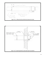
Page 31: ...31 Figure 7 33c Cutting Inner Pipe of 80 125mm Horizontal Terminal Figure 7 33d Completing 80 125mm Horizontal Terminal Installation ...

Page 32: ... install the lower wall bracket b Before mounting the lower wall bracket loosen the M10 x 35 screw on this bracket Adjust this bolt forward or backward so that its center is 6 7 16 from the wall Figure 7 34 and tighten c Center the Lower Wall Bracket on the hole in the wall and mark the location of the four mounting screws on the wall 5 16 mounting screws not supplied are recommended for mounting ...

Page 33: ...d for this installation a Determine the center line of the terminal location on the roof If the roof is flat cut a 5 1 2 diameter hole for the terminal If the roof is sloped cut a hole large enough for the terminal to pass through the roof while remaining plumb Caution If the boiler is installed directly under the hole cover it while cutting the hole to prevent saw dust and other debris from falli...

Page 34: ...34 Figure 7 35b Cutting Vertical Terminal Figure 7 35c Completing Vertical Terminal Installation ...

Page 35: ... back of the support bracket on the back wall of the chimney Drill a 7 16 dia x 2 1 2 deep hole at this location to support the back of the bracket The front of the elbow mounting bracket is supported by the bottom of the opening into the chimney or by an installer supplied bracket b Construct a weather tight flat roof to cover the top of the old chimney Install the vertical terminal through this ...

Page 36: ...d not be placed at the bottom of horizontal sections of exhaust pipe c Do not drill holes in vent pipe d Do not attempt to mix vent components of different vent system manufacturers 2 Mounting Stainless steel vent collar The use of stainless steel venting requires the stainless steel vent collar P N 101004 01 which replaces the 80 125mm concentric collar supplied with the boiler To install the sta...

Page 37: ...he inside of the vent collar on the boiler Remove dirt grease and moisture from the surfaces to be sealed Dry surfaces or allow to dry thoroughly d On the male end of the pipe apply a wide bead of silicone approximately from the end of the pipe see Figure 7 47 e Insert the male end of the pipe into the boiler vent collar until it bottoms out f Apply an additional bead of silicone over the outside ...

Page 38: ...ately inch from the male end of the pipe Apply beads of silicone along both sides of the longitudinal seam Figure 7 48 e Insert the male end of the pipe into the boiler vent collar until it bottoms out f Apply an additional bead of silicone over the outside of the joint and smooth out g Replace and tighten the clamp on the vent collar h The female end of each Z Vent III component has a silicone se...

Page 39: ... pipe so that it can be inserted at least 1 into the collar Clean the exterior of the male end of the first piece of pipe and the inside of the vent collar on the boiler with an alcohol pad On the male end of the pipe apply a wide bead of high temperature silicone approximately inch from the male end of the pipe Also apply a bead of silicone along the first 2 of the longitudinal weld Insert the ma...

Page 40: ...venting system rely on a gasket in the female end of the pipe for a proper seal d Align the longitudinal seam of both pipes Insert the male end of the second pipe into the female end of the first pipe until the bead on the male end contacts the flare on the female end e Tighten the locking band with a nut driver f Repeat d and e for the remaining FasNSeal components g Allow the silicone to cure pe...

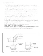
Page 41: ...t be installed as shown in Figure 7 51 A length of drain hose is supplied with the boiler and is connected to the trap as shown in Figure 7 51 Note the following when disposing of the condensate a If the condensate drain line must be extended construct the extension from PVC or CPVC pipe Insert the hose provided with the boiler into the end of the extension as shown in Figure 7 51 b Condensate is ...

Page 42: ...42 FIGURE 7 51 CONDENSATE PIPING ARRANGEMENT ...

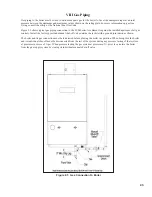
Page 43: ...ed upstream of all gas controls Install the factory provided manual shut off valve outside the jacket with a ground joint union as shown The boiler and its gas connection must be leak tested before placing the boiler in operation When doing this the boiler and its individual shut off must be disconnected from the rest of the system during any pressure testing of that system at pressures in excess ...

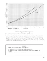
Page 44: ...LISTED IN PART XI OF THIS MANUAL MAINTAIN THE PRESSURE IN THE BOILER AT A MINIMUM OF 12 PSI DESIGN SYSTEM TO ENSURE THAT THE FLOW FALLS WITHIN THE LIMITS CALLED FOR IN TABLE 9 1 B System Design Proper operation of the FCM boiler requires that the water flow through the boiler remain within the limits shown in Table 9 1 any time the burner is firing Failure to maintain the flow within these limits ...

Page 45: ...e result is the total equivalent length of the secondary loop d Using Table 9 5 find the boiler size being installed and select a boiler secondary circulator that shows a maximum equivalent length column e in excess of the total equivalent length calculated in Step 2c 3 Indirect Water Heater Loop Piping If Indirect Water Heater is Used All piping must be the size shown in Table 9 6 column a If the...

Page 46: ...ves Calculate total equivalent length from Table 9 7 20 Straight Pipe 5 Elbows x 2 75 2 Turns in Tees x 5 5 1 Swing Check x 7 2 valves x 0 6 52 95 Equivalent Feet Straight Pipe From Table 9 6 we see that smallest circulator which will pump at 8 GPM through a FCM120 with 52 95 equivalent feet and an indirect water heater pressure drop of 3 ft is a Taco 0014 ...

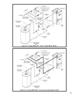
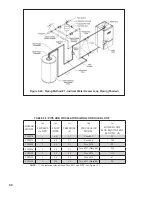
Page 47: ...47 Figure 9 3 Piping Method 1 Heat Indirect Water Heater Figure 9 4a Piping Method 1 Secondary Loop Piping Shaded ...

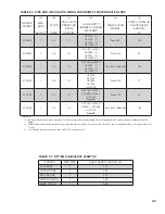
Page 48: ...T FLOW GPM TEMP RISE F CIRCULATOR MODEL BOILER LOOP MAX EQUIVALENT LENGTH ft FCM070 1 6 0 22 Taco 007 55 FCM070 1 6 0 22 Taco 008 145 FCM090 1 8 0 21 Taco 0014 90 FCM090 1 8 0 21 Taco 0013 Note 1 230 FCM120 1 8 0 29 Taco 0014 111 FCM120 1 9 0 25 Taco 0014 61 FCM120 1 12 0 19 Taco 0013 Note 1 28 NOTE 1 Use isolation relay between Taco 0013 and FCM see Figure 10 3 ...

Page 49: ...014 71 FCM120 1 8 0 5 0 AL27SL AL35SL AL50SL AL70SL AL119SL Note 2 Taco 0014 45 FCM120 1 8 0 5 0 AL27SL AL35SL AL50SL AL70SL AL119SL Note 2 Taco 0013 Note 3 185 NOTES 1 Indirect water heaters with an asterisk will not achieve their catalog rating due to inadequate boiler water flow and or inadequate boiler output 2 When used with an indirect heater having a pressure drop less than 3 0 ft of head t...

Page 50: ...ult to accurately calculate the pressure drop through the system In replacement installations it may be impossible to get an accurate measurement of the amount of piping and number of fittings in the system In addition if the system is zoned the system flow may drop well below the minimum required when only one zone is calling for heat The one advantage to this method is its installation simplicit...

Page 51: ...eate a hazard or cause property damage if the valve opens The end of the discharge pipe must terminate in an unthreaded pipe If the relief valve discharge is not piped to a drain it must terminate at least 6 inches above the floor Do not run relief valve discharge piping through an area that is prone to freezing The termination of the relief valve discharge piping must be in an area where it is no...

Page 52: ...Isolation valves are useful when the boiler must be drained as they will eliminate having to drain and refill the entire system 9 Drain Valve Required The drain valve is installed on the return tee located in the lower vestibule compartment as shown in Figure 9 2 10 Low Water Cut off Required The low water cut off supplied with this boiler must not be removed D Piping for Special Situations 1 Syst...

Page 53: ...53 Figure 9 11 Chiller Piping Figure 9 10 Isolation of the Boiler From Oxygenated Water with A Plate Heat Exchanger ...

Page 54: ...ance with the authority having jurisdiction or in the absence of such requirements with the National Electrical Code ANSI NFPA 70 X Wiring CAUTION WHEN MAKING LOW VOLTAGE CONNECTIONS MAKE SURE THAT NO EXTERNAL POWER SOURCE IS PRESENT IN THE THERMOSTAT OR LIMIT CIRCUITS IF SUCH A POWER SOURCE IS PRESENT IT COULD DESTROY THE BOILER S MICROPROCESSOR CONTROL MCBA ONE EXAMPLE OF AN EXTERNAL POWER SOURC...

Page 55: ...55 Figure 10 1 Wiring Connections Diagram ...

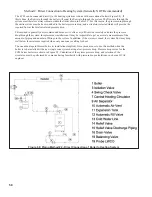
Page 56: ...56 Figure 10 2 Ladder Diagram ...

Page 57: ...57 Figure 10 3 Wiring of Isolation Relay for Control of Two Heating Circulators ...

Page 58: ...ormation on testing and purging gas lines 4 Vent system must be complete and free of obstructions before attempting to fire boiler Make sure that the silicone cure time called for in the vent assembly instructions has passed before firing boiler 5 Inspect all line voltage wiring for loose or uninsulated connections 6 Remove the dust cap from the condensate trap Figure 7 51 Add water to the trap un...

Page 59: ...oroughly for leaks before placing it in service If the system includes underground piping or other piping in which a leak might go undetected consider isolating the boiler from the system with a heat exchanger Alternatively consider installing a water meter in the fill line to record additions of make up water Make sure that the expansion tank is properly sized and in good condition If it is not t...

Page 60: ...60 FCM Series Lighting and Operating Instructions ...

Page 61: ...Temp No call for heat After call for heat from heating thermostat 3 A SWT Self Check on Start up 4 5 SWT Blower and circulator on Checking for adequate air flow 5 1 SWT Prepurge 6 2 SWT Trial for ignition 7 3 SWT Flame established Boiler responding to a call for heat 8 Upon initial start up the gas train will be filled with air Even if the gas line has been completely purged of air it may take sev...

Page 62: ...button until the display flashes H indicating that the boiler has been driven to high fire After this happens allow the boiler to operate for approximately 5 minutes before taking combustion readings b To lock the boiler in low fire simultaneously press and hold the Mode button and button until the display flashes L indicating that the boiler has been driven to low fire After this happens allow th...

Page 63: ...ns 13 Verify that the boiler starts and stops in response to calls for heat from the heating thermostat and indirect water heater thermostat Make sure that the appropriate circulators also start and stop in response to the thermostats 14 As shipped the heating and indirect water heater set point supply temperatures are both set to 180 F If necessary adjust these to the appropriate settings for the...

Page 64: ...fety controls including the low water cut off and safety limit are connected into the MCBA The MCBA uses input from all of these controls to either shut down the boiler when an unsafe condition exists or in some cases to correct the problem 2 The display panel has three primary modes of operation These are Standby Mode Displays boiler s current status This is the default operating mode Parameter M...

Page 65: ...mbustion tests After 15 minutes the burner will automatically revert to modulation If it is desired to revert to modulation before 15 minutes has passed simultaneously pushing and will restore modulation In Parameter mode both set points can be changed and both zones turned on or off In addition both zones can be configured for continuous pump operation If the heating zone is set for continuous pu...

Page 66: ...66 FIGURE 12 2 BASIC MENU TREE ...

Page 67: ...e in Figure 12 4 The maximum set point is defined by parameter 4 factory set to 180 F when the outdoor temperature is 0 F or below The minimum set point temperature shown is 100 F when the outdoor temperature is 60 F or above As the outdoor temperature falls the supply water target temperature increases For example if the outdoor air temperature is 30 F the set point temperature for the supply wat...

Page 68: ... the set point temperature and the supply temperature If an outdoor sensor is connected to the control module and the boiler is responding to a call for heat the set point temperature will be determined by the outdoor reset curve shown in Figure 12 4 f Once the set point temperature is reached the MCBA will turn the burner off and allow the combustion fan to operate in postpurge for 35 seconds bef...

Page 69: ...es to verify they are free from leaks Call the service technician to make repairs if required 4 Annual Inspections and Service In addition to the inspections listed above the following should be performed by a service technician once every year a Test the low water cutoff by pressing the Test button located at its end The yellow light should come on and E12 should flash on the display Push the res...

Page 70: ...ion replace it immediately Inspect the burner gasket and replace if necessary h Inspect the heat exchanger and vacuum any debris found on the pins and other surfaces Clean the casting pins by flushing with clean water A soft nylon brush may be used in accessible areas Drain and flush the inside of the heat exchanger and condensate collector as required Do not use any cleaning agents or solvents i ...

Page 71: ...location Replace with 5A fuse provided Display reads U 125 continuously Fan running Defective AT250 transformer Blown F3 fuse in MCBA see Figure 14 2 for location Replace with 4A slow blow fuse provided Boiler not responding to call for heat Status code on display 0 see Figure 11 1 Boiler is not seeing call for heat Check thermostat or zone wiring for loose connection miswiring or defective thermo...

Page 72: ...s purged of air and that appropriate valves are open Sensor wiring reversed Supply or return sensor defective b 25 Supply water temperature has risen too quickly See possible causes for b18 Inadequate boiler water flow Verify that pump is operating and that pump and piping are sized per Part VIII of this manual b 26 Boiler safety limit or external limit wired across terminals 3 4 is open See possi...

Page 73: ... proper operation E 19 MCBA return sensor detected temperatures in excess of 200 F for an extended period of time See possible causes for b19 error E 28 Blower is not running when it should or fan speed signal not being detected by MCBA Loose connection in 120 VAC fan wiring Loose or miswired fan speed harness Defective fan E 29 Blower fan speed has not returned to zero rpm Miswired fan speed harn...

Page 74: ... local Burnham Wholesale distributor Should you require assistance in locating a Burnham distributor in your area or have questions regarding the availability of Burnham products or repair parts please contact Burnham Customer Service at 717 481 8400 or Fax 717 481 8408 ...

Page 75: ...75 ...

Page 76: ...auge Cap Tube Clamp 1 100377 01 1 100377 01 1 100377 01 17 High Limit 1 100517 01 1 100517 01 1 100517 01 18 Burner 1 101165 01 1 101165 01 1 101050 01 19 Burner Hood Gasket 1 100378 01 1 100378 01 1 100378 01 20 5 x 8 Grooved Pin 2 100379 01 2 100379 01 2 100379 01 21 Burner Hood FCM 1 100380 01 1 100380 01 1 100380 01 22 Burner Hood Cover Plate Gasket 1 100381 01 1 100381 01 1 100381 01 23 Burne...

Page 77: ...77 ...

Page 78: ... 01 1 101051 01 73 42 5mm Short Fan Adpator Plate 1 101052 01 1 101052 01 1 101052 01 74 M4 x 25mm Flat Head Machine Screw 3 101053 01 3 101053 01 3 101053 01 75 9mm Swirlplate Red 1 101054 01 5mm Swirlplate Blue 1 101166 01 1 101166 01 76 Dungs Air Inlet Adaptor Part 1 female 1 101055 01 1 101055 01 1 101055 01 77 M4 x 10mm FH Machine Screw 4 101056 01 4 101056 01 4 101056 01 78 Injector Plate 1 ...

Page 79: ...79 ...

Page 80: ...80 ...

Page 81: ...81 ...

Page 82: ...1068 01 4 101068 01 4 101068 01 132 Rubber Bumper 2 101069 01 2 101069 01 2 101069 01 133 Pinhole Grommet 2 101070 01 2 101070 01 2 101070 01 134 Draw Keeper 2 101071 01 2 101071 01 2 101071 01 135 Bottom Panel 1 101072 01 1 101072 01 1 101072 01 136 Bottom Pan Support Bracket 1 101073 01 1 101073 01 1 101073 01 137 FCM Door Gasket 1 101074 01 1 101074 01 1 101074 01 138 Upper Front Jacket Panel 1...

Page 83: ...83 150 151 152 153 154 155 ...

Page 84: ...84 156 157 158 159 160 161 ...

Page 85: ...85 162 ...

Page 86: ... subdivision can not be met at the time of completion of installation the owner shall have a period of thirty 30 days to comply with the above requirements provided however that during said thirty 30 day period a battery operated carbon monoxide detector with an alarm shall be installed 2 APPROVED CARBON MONOXIDE DETECTORS Each carbon monoxide detector as required in accordance with the above prov...

Page 87: ...equirements shall be satisfied by the manufacturer 1 The referenced special venting system instructions shall be included with the appliance or equipment installation instructions and 2 The special venting systems shall be Product Approved by the Board and the instructions for that system shall include a parts list and detailed installation instructions e A copy of all installation instructions fo...

Page 88: ...ends the following limited warranties to the original owner of a residential grade cast aluminum water boiler manufactured and shipped on or after January 1 2006 U S Boiler Company Inc warrants to the original owner that its residential grade cast aluminum water boilers comply at the time of manufacture with recognized hydronic industry standards and requirements then in effect and will be free of...

Reviews: