background image

30

SERVICE (cont.)

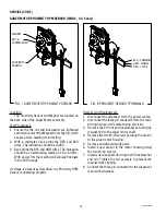
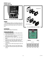
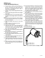
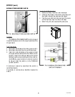
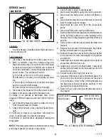
FROTHER AND WHIPPER MOTOR

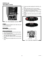
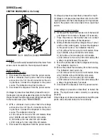
FIG. 29 FROTHER AND WHIPPER MOTOR

P1641.40

Location:


The frothers are located behind the dispenser door, 

mounted on the whipper motor shaft inside the whipper 

chamber.


The whipper motors are located on the back side 

of the whipper motor mounting panel.

Test Procedure:

1.  Check that the rinse/run switch is in the rinse (up) 

position.

2.  Disconnect the dispenser from the power source.

3.  Disconnect both wires from the black leads on the 

motor to be checked.

4.  Press  and  hold  the  appropriate  dispense  switch 

and, with a voltmeter, check the voltage across the 

disconnected harness. Connect the dispenser to the 

power source. The reading must be:


a) 120 volts ac for two wire 120 volt models, three 

wire 120/208 volt and 120/240 volt models.


b) 240 volts ac for two wire 240 volt models.


c) 230 volts ac for two wire 230 volt models.

5.  Disconnect the dispenser from the power source.

If voltage is present as described, replace the motor.

If voltage is not present as described, refer to the 

Wiring 

Diagrams

 and check the dispenser wiring harness

9        8      7   6     5    4    3

10

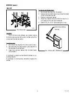
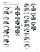
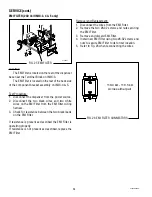
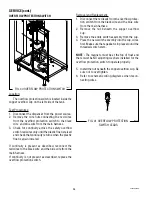
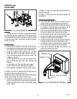
FIG. 30 MIXING/WHIPPER CHAMBER 

COMPONENTS

P1630.35

1.   Steam Collector

2.   Mixing Chamber 

3.   Dispense Tip

4.   Whipper Chamber

5.   O-Ring

6.  Frother

7.   Nut

8.  Receptacle w/Seal

9.   Slinger

10.  Motor Assy.

11.  Fan

12.  Vacuum Hose

13.  Baffle

11   12   13

1     2

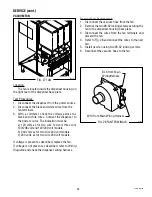
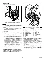
Removal, Cleaning & Replacement (Refer to Fig. 30):

1.  Disconnect the dispenser from power.

2.  Open the dispenser door and turn elbows up.

3.  Remove the steam collectors (1) by pulling forward 

and at the same time twisting clockwise.

4.  Pull  the  mixing  chamber  (2)  out  of  the  whipper 

chamber (4).

5.  Remove  dispense  tip  (3)  and  twist  the  whipper 

chamber (4) clockwise and pull it off the whipper 

chamber receptacle (8).

42032 060109

Summary of Contents for IMIX

Page 1: ...SERVICE REPAIR MANUAL BUNN O MATIC CORPORATION POST OFFICE BOX 3227 SPRINGFIELD ILLINOIS 62708 3227 PHONE 217 529 6601 FAX 217 529 6644 42032 0000A 06 09 2009 Bunn O Matic Corporation IMIX IMIX S ...

Page 2: ... binding on BUNN Accordingly statements by such individuals whether oral or written do not constitute warranties and should not be relied upon If BUNN determines in its sole discretion that the equipment does not conform to the warranty BUNN at its exclusive option while the equipment is under warranty shall either 1 provide at no charge replacement parts and or labor during the applicable parts a...

Page 3: ...atics 42 Site preparation A minimal clearance is required between the dispenser sides and the wall or another appliances Leave some space so the dispenser can be moved for cleaning INTRODUCTION Safety first To avoid electrical shock unplug dispenser from power source before servicing inside Basic Maintenance In order to maintain proper machine operation a Preventative Maintenance schedule must be ...

Page 4: ...a deberá realizarse diariamente 1 x 7d 1 2 3 4 5 a Wash b Rinse c Sanitize d Dry a Lave b Enjuague c Desinfecte d Seque 7 8 6 a b c 9 7 Replace Light Bulbs as required 1 Para limpiar las camaras de mezcla coloque el interruptor en la posicón ENJUAGUE MARCHA RINSE RUN y pulse el boton para espumar y distribuir la bebida DISPENSE 2 Gire el codo hacia arriba remueva las tolvas llene las tolvas con pr...

Page 5: ... be set using the Rinse Alarm Check and or replace every 6 months or as required 32906 0001 Mixing Chamber Kit Includes items indented below 25732 0000 Steam Collector 25733 0003 Mixing Chamber 25734 0000 Whipper Chamber 25736 0000 Dispense Tip 24733 0010 O ring 25902 0000 Frother 26356 0000 Shaft Seal 28866 0000 Receptacle 25903 0000 Elbow Check and or replace every 3 months or as required 26356 ...

Page 6: ...MEDY Product will not dispense no water and no powder 2 3 7 11 yes water and no powder 6 9 10 12 no water and yes powder 1 4 5 8 1 No water 2 No power or incorrect voltage to the dispenser 3 Dispense switch 4 Dispense solenoid valve 5 Solenoid valve inlet 6 Auger drive 7 Overflow protection Switch 8 Lime build up 9 Hopper not seated on panel 10 Hopper out of product 11 Rinse cycle not run within p...

Page 7: ...CAL tank temp under CALIBRA TION menu Test triac use TANK HEATER under DIAG NOSTICS menu Disconnect wire leads from tank heater check for continuity across tank heater leads Inspect tank assembly for excessive lime depos its Delime as required A Check tank temperature setting in Program ming menu B Check temperature probe function and cali bration see CAL tank temp under CALIBRA TION menu Inspect ...

Page 8: ...f front door Check that switch is set in the NORMAL posi tion Refill hopper with correct product Check throw weight Plumbing lines should not be resting on the counter top Water pressure to the dispenser not to exceed 90 psi 620 kPa Install a regulator if necessary to lower the working pressure to approximately 50 psi 345kPa Remove and clean lime off tank heater Check for cleanliness and correct i...

Page 9: ...120 minutes refill does not come on and tank is still below target temperature Occurs when overflow cup is full of wa ter Occurs when tank sensor is disconnected or resistance to high Occurs when tank temperature sensor wires are shorted together or resistance is to low Occurs when auger motor should be run ning but no pulses are detected from the RPM sensor Occurs if display communication lost No...

Page 10: ...10 42032 060109 NOTES ...

Page 11: ...removal of any panel or the replacement of any component All components are accessible by opening the door removal of the door panels dispenser top covers hopper s hopper support plate splash guard splash panel w drip tray lower front access panel and rear ac cess cover Refer to the contents listing for component location Index Access Panels 12 Audio Indicator 13 Auger Drive Components 14 Ballast ...

Page 12: ...through the whole IMIX family IMIX 5 shown Before removing panels make sure power is OFF to the machine and water is disconnected accept where indicated in testing procedures Retain all screws and other attaching hardware for re assembly FIG 1 Access panels 42032 060109 ...

Page 13: ...er from power 2 Disconnect the two pin connector from J8 of the main control board 3 Loosen two screws from underneath and remove the component mounting bracket 4 Remove the two 6 32 screws attaching the Audio Indicator to the component mounting bracket 5 Remove and discard the audio indicator 6 Install new audio indicator using two 8 32 screws to secure indicator to the component bracket 7 Refer ...

Page 14: ...ect YES 3 Scroll to Test Augers 4 Press the appropriate dispense switch to activate motor Refer to Diagnostics for further direction Removal Cleaning and Replacement Hopper Auger 1 Open the dispenser door and turn elbow up 2 Lift the front edge of hopper assy over the tab on hopper support plate 16 and slide hopper as sembly out the front of the dispenser 3 Remove hopper lid 1 and empty product 4 ...

Page 15: ...on the front of the auger motor mounting panel 11 securing auger motor 13 to the rear of the auger motor mounting panel 11 4 Disconnect the wires from the auger motor 13 to be removed 5 Disconnect RPM sensor plug 6 Remove auger motor 13 and dust seal 14 as an assembly 7 Remove dust seal 14 from auger motor 13 8 Removethe 8 32screwssecuringtheaugermotor to the auger motor mounting bracket 9 Remove ...

Page 16: ...reading of 5 0 5 0VDC With power ON the reading will actually fluctuate in the 3VDC range If voltage is present as described the Proximity RPM Sensor is operating properly Removal and Replacement 1 Disconnect the dispenser from the power source 2 Disconnect the three pin connector from the main wirring harnes of the motor being serviced 3 Remove the 10 nut and lockwasher securing the magnet hub to...

Page 17: ...n the two black leads on the ballast If continuity is present as described the ballast is op erating properly If continuity is not present as described replace the ballast Removal and Replacement 1 Disconnect the wires from the ballast 2 Remove the two 8 32 screws securing the ballast to the component bracket 3 Remove and discard ballast 4 Install new ballast using two 8 32 screws to se cure balla...

Page 18: ...escribed refer to the Wir ing Diagrams and check the dispenser wiring harness back to the power cord Also check for an open float switch Liquid Level Control Circuitry 6 Gently pull the liquid level probe out of the tank lid and inspect for corrosion Replace it if necessary 7 Place the probe so that neither end is in contact with any metal surface of the dispenser 8 Withavoltmeter checkthevoltagea...

Page 19: ...nnectalltheplugsonthemainwiringharness from the connectors on the control board 4 Removethefour 6 32screwssecuringthecontrol board to the component bracket 5 Remove the spacers from the control board and discard 6 Install the spacers on to the new control board 7 Installnewcontrolboardonthecomponentbracket using four 6 32 screws NOTE Verify the ground wire is connected to the board mounting screw ...

Page 20: ...s ac for two wire 230 volt models 5 Disconnect the dispenser from the power source 42032 060109 If voltage is present as described proceed to step 6 Ifvoltageisnotpresentasdescribed refertothewiring diagram and check the dispenser wiring harness back to the power cord 6 Gently pull the liquid level probe out of the tank lid and inspect for corrosion Replace it if necessary 7 Place the probe so tha...

Page 21: ...ss from the connectors on the control board 2 Remove the four 6 32 keps nuts securing the control board to the component bracket 3 Remove control board and discard 4 Installnewcontrolboardonthecomponentbracket using four 6 32 keps nuts 5 Reconnect the three plugs on the main harness to the connectors on the control board CONTROL BOARD cont ...

Page 22: ...s securing the lower door panel and remove the panel 4 Disconnect the touchpad harness from the display board 5 Carefully peel the touchpad from the front of the door J9 1 J9 7 TOUCHPAD PUSH BUTTON PORTION CONTROL DISPLAY BOARD Digital Beverage Control STOP 42032 060109 6 Remove any excess adhesive from the door sur face 7 Remove the backing from the new touchpad 8 Feed the seven pin harness throu...

Page 23: ... returns to main screen Adjust tank temperature Adjust minimum tank ready temperature for lockout To Diagnostics XX CAL XX Tank Temp SELECT UNITS ENG EXIT METRIC Calibration 235 REFILL 155 EXIT CAL WATER 1 PRESS DISPENSE ENTER VOLUME 1 XX X oz CAL POWDER 1 PRESS DISPENSE ENTER WEIGHT 1 XX X gm Auger Delay XX sec CAL HOPPER 1 NO YES Goes to next station Continues after last station TEST SWITCHES Us...

Page 24: ...s operating properly If voltage is present as described replace the memory board Removal and Replacement 1 Disconnect the wiring harness from the memory board 2 Remove the two 6 32 screws securing the mem ory board to the component bracket 3 Remove the two spacers from the memory board 4 Remove and discard memory board 5 Install the two spacers to the new memory board 6 Install new memory board us...

Page 25: ...s for the black and white wires 9 See the chart for resistance readings 10 Verify wiring to probe 11 If readings are not present as described replace the temperature probe NOTE Some meters have difficulty measuring a sen sor either rapidly rising or falling in temperature Removal and Replacement 1 Disconnect the dispenser from the power source 2 Remove the top rear cover 3 Disconnct the two pin co...

Page 26: ... orange for the left dispense switch from the door interconnect wiring harness Connect the dispenserto thepower source Theindicationmust be 5 volts dc If voltage is present as described proceed to 7 Ifvoltageisnotpresentasdescribed refertotheWiring Diagrams and check the dispenser wiring harness 7 Check for continuity across the terminals top right to top left bottom right to bottom left of the di...

Page 27: ...2 Open the dispenser door 3 Remove the four 8 32 screws securing the lower door panel and remove the panel 4 Disconnect the five pin harness from the switch board 5 Remove the four 6 screws securing the switch board to the door frame and discard the board 6 Other parts of the switch assembly may be removed if necessary 7 Install the new switch board using the four 6 screws 8 Connect the five pin h...

Page 28: ...the EMI Filter wiring harness 3 Check for resistance between the two black leads on the EMI Filter If resistance is present as described the EMI Filter is operating properly If resistance is not present as described replace the EMI Filter Removal and Replacement 1 Disconnect the wires from the EMI Filter 2 Remove the two 8 32 screws and nuts securing the EMI Filter 3 Remove and discard EMI Filter ...

Page 29: ...or two wire 240 volt models c 230 volts ac for two wire 230 volt models If voltage is present as described replace the fan If voltage is not present as described refer to Wiring Diagrams and check the dispenser wiring harness SERVICE cont Removal and Replacement 1 Disconnect the vacuum hose from the fan 2 Remove the two 8 32 locking screws securing the fan to the dispenser housing base plate 3 Dis...

Page 30: ...models b 240 volts ac for two wire 240 volt models c 230 volts ac for two wire 230 volt models 5 Disconnect the dispenser from the power source If voltage is present as described replace the motor If voltage is not present as described refer to the Wiring Diagrams and check the dispenser wiring harness 9 8 7 6 5 4 3 10 FIG 30 MIXING WHIPPER CHAMBER COMPONENTS P1630 35 1 Steam Collector 2 Mixing Ch...

Page 31: ...ng in the dispenser 17 Slidewhipperchamberreceptaclewithseal 8 and o ring 5 on to the motor shaft 18 Rotatethereceptaclewithseal 8 counterclockwise untilitsnapsintoplaceonthemotormountingnuts 7 19 Push frother 6 onto the motor shaft making sure the flat in the frother 6 lines up with the flat on the motor shaft 20 Installwhipperchamber 4 onthewhipperchamber receptacle 8 by twisting counterclockwis...

Page 32: ...window to the door and remove window 3 Pull the lamp upwards and remove from the lamp holders 4 Remove lamp from lamp holders 5 Remove the two lower screws attaching the lamp holder bracket and remove the bracket 6 Disconnect the lamp holder from the lamp panel 7 Disconnectthewiringharnessfromthelampholder to be replaced and discard 8 Connect the wiring harness to the new lamp holder and snap the ...

Page 33: ... limit thermostat terminals SERVICE cont Ifcontinuityispresentasdescribed thelimitthermostat is operating properly If continuity is not present as described replace the limit thermostat Removal and Replacement 1 Remove all wires from the limit thermostat termi nals 2 Carefully slide the limit thermostat out from under the retaining clip and remove the limit thermo stat 3 Carefully slide the new li...

Page 34: ...ition Check for continuity between the center terminal and the lower terminal with the switch in the ON upper position Continuity must not be present when the switch is in the OFF center position If continuity is present as described the switch is operating properly If continuity is not present as described replace the switch Removal and Replacement 1 Remove all wires from the switch terminals 2 C...

Page 35: ...SE lower position Check for continuity between the center terminal and the lower terminal with the switch in the NORMAL upper position Continuity must not be present when the switch is in the PROGRAM center position If continuity is present as described the switch is operating properly If continuity is not present as described replace the switch Removal and Replacement 1 Remove all wires from the ...

Page 36: ... as described reconnect the red wires to the black wire and the blue wire from the main harness If continuity is not present as described replace the overflow protection switch Removal and Replacement 1 Disconnect the red leads from the overflow protec tion switch from the black wire and the blue wire from the main harness 2 Remove the nut beneath the copper overflow cup 3 Remove the entire switch...

Page 37: ... the sound is heard as described and water will not pass through the solenoid valve there may be a block age in the water line before the solenoid valve or the solenoid valve may require inspection for wear and removal of waterborne particles If the sound is not heard as described replace the solenoid valve Removal and Replacement 1 Remove the two wires from the solenoid valve 2 Turn off the water...

Page 38: ... for coil action Connect the dispenser to the power source With RUN RINSE switch in the RINSE upper position press the appropriate dispense switch and listen carefully in the vicinity of the solenoid valve for a clicking sound as the coil magnet attracts 7 Disconnect the dispenser from the power source If the sound is heard as described and water will not pass through the solenoid valve there may ...

Page 39: ...sheath Removal and Replacement 1 Shut off water supply to the dispenser 2 Disconnect the water supply tube on the tank lid 3 Disconnect the black wires on the limit thermo stat 4 Disconnect the black wire and the white or red wire from the tank heater terminals 5 Disconnect the pink wire from the liquid level probe 6 Disconnect the green wire from the tank 7 Remove the thermostat capillary bulb te...

Page 40: ...FORMER FIG 48 TRANSFORMER Location The transformer is mounted on the side of the tank mounting bracket for models 3 4 5 The transformer islocatedbehindthelowerfrontaccesscover mounted on the rear side of the component bracket for models 3S 3S 5S 5S Test Procedure 1 Disconnect the dispenser from the power source 2 Disconnectthefourpinplugfromthemainharness from the four pin connector on the transfo...

Page 41: ...connect the dispenser from the power source 2 Disconnectthetwopinconnectorfromthedispenser main wiring harness 3 Disconnect the BLU wire from ther limit thermo stat 4 Disconnect the BLK wire from the terminal block 5 Remove the two 6 32 screws attaching the heat sink to the tank mounting bracket and remove the heat sink assembly 6 Removethe 6 32screwandlockwasherattaching the triac to the heat sin...

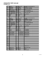
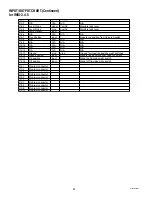
Page 42: ...Gnd DC ground Self explanatory J3 12 N A N A N A N A J3 13 N A N A N A N A J3 14 N A N A N A N A J4 1 Auger 2 Output 0 to 24 VDC Adjustable to change dispense rate J4 2 RPM sensor Input Signal Hall Effect J4 3 RPM sensor Output 5 VDC Power supply to Hall Effect J4 4 RPM sensor Output Negative Power supply to Hall Effect J4 5 N A N A N A N A J4 6 Dispense Whipper Output N or L2 Nuetral or second le...

Page 43: ...7 6 Dispense Whipper Output N or L2 Nuetral or second leg J7 7 Dispense Whipper Output L1 Leg 1 activated with dispense J7 8 Low powder detect J7 9 Low powder detect Output 5 VDC Sensor power supply J7 10 Low powder detect J7 11 Ground Gnd DC ground Self explanatory J7 12 N A N A N A N A J7 13 N A N A N A N A J7 14 N A N A N A N A J8 1 Beeper Output 8 VDC Self explanatory J8 2 Beeper Output Ground...

Page 44: ... N A N A N A N A J12 13 Ground grnd grnd Ground for rinse run and day night switches J12 14 Rinse position Input Signals rinse position from rinse run switch J12 15 On position Input Signal on from day night switch J12 16 Off position Input Signal off from day night switch J13 1 Program connector J13 2 Program connector J13 3 Program connector J13 4 Program connector J13 5 Program connector J13 6 ...

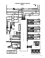
Page 45: ... WHI GRN WHI RED WHI GRN WHI WHI GRN BEEPER RED BLK BLK PROBE ON OFF NIGHT RUN PROGRAM RINSE WHI GRN WHI YEL WHI VIO WHI BLU GRN RED ORN BLU WHI GRN GRN 1 t WHI BLK J1 1 J1 5 J2 1 J2 5 J3 1 J3 5 J1 1 J1 5 J2 1 J2 5 J3 1 J3 5 J10 4 J10 1 DISPLAY BOARD SWITCH BOARD SWITCH BOARD SWITCH BOARD BLU YEL ORN BLK RED BLU YEL ORN BLK RED BLU YEL ORN BLK RED J9 1 J9 7 TOUCHPAD 1 AUGER MOTOR SPEED SENSOR 1 1 ...

Page 46: ...46 42032 060109 ...

Page 47: ... t WHI BLK J1 1 J1 5 J2 1 J2 5 J3 1 J3 5 J4 1 J4 5 J5 1 J5 5 J1 1 J1 5 J2 1 J2 5 J3 1 J3 5 J4 1 J4 5 J5 1 J5 5 DISPLAY BOARD SWITCH BOARD SWITCH BOARD SWITCH BOARD SWITCH BOARD SWITCH BOARD BLU YEL ORN BLK RED BLU YEL ORN BLK RED BLU YEL ORN BLK RED BLU YEL ORN BLK RED BLU YEL ORN BLK RED J9 1 J9 7 TOUCHPAD 1 AUGER MOTOR SPEED SENSOR 1 1 HOPPER EMPTY DETECT SENSOR 1 M SOL DISPENSE VALVE 1 M AUGER ...

Page 48: ...48 42032 060109 ...
Page 49: ...hipper 4 Output L1 activated with dispense J4 6 Dispense Whipper 5 Output L1 activated with dispense J4 7 N A N A N A N A J4 8 Temp Sensor GRND GND J4 9 Level Probe GRND GND J4 10 N A N A N A N A J4 11 Temp Sensor Input 0 to 5 VDC Monitors tank temperature J4 12 Rinse position Input 0VDC in rinse Signals rinse position from rinse run switch J4 13 Inlet Output 120 VAC Inlet activated with refill ci...

Page 50: ...HIPPER 1 BRN BLK BRN BLK RED RED ORN ORN YEL YEL BLU BLK GRN WHI NOT USED ON IMIX 3S MODELS NOT USED ON IMIX 3S MODELS NOT USED ON IMIX 3S MODELS TANK HEATER BLU BLK 16 BLU BLK 16 WHI YEL GRY RED BLK WHI GRY GRY RED BLK WHI WHI WHI WHI WHI WHI WHI WHI WHI WHI WHI WHI WHI WHI WHI WHI WHI WHI WHI GRN WHI VIO PNK SOL DISPENSE VALVE 2 M WHIPPER 2 SOL DISPENSE VALVE 3 M WHIPPER 3 SOL DISPENSE VALVE 4 M...

Page 51: ...EL YEL BLU BLK GRN WHI NOT USED ON IMIX 3S IMIX 3S A MODELS NOT USED ON IMIX 3S IMIX 3S A MODELS NOT USED ON IMIX 3S MODELS TANK HEATER WHI YEL GRY RED BLK WHI GRY GRY RED BLK WHI WHI WHI WHI WHI WHI WHI WHI WHI WHI WHI WHI WHI WHI WHI WHI WHI WHI WHI GRN WHI VIO PNK SOL DISPENSE VALVE 2 M WHIPPER 2 SOL DISPENSE VALVE 3 M WHIPPER 3 SOL DISPENSE VALVE 4 M WHIPPER 4 SOL DISPENSE VALVE 5 M WHIPPER 5 ...

Page 52: ... BLU BLK 16 BLU BLK 16 BLK 16 WHI YEL GRY RED RED BLK BLK WHI GRY GRY RED BLK WHI WHI WHI WHI WHI WHI VIO WHI WHI WHI WHI WHI WHI WHI WHI WHI WHI WHI WHI WHI WHI WHI WHI WHI WHI VIO WHI GRN WHI VIO PNK PNK PNK SOL DISPENSE VALVE 2 M WHIPPER 2 SOL DISPENSE VALVE 3 M WHIPPER 3 SOL DISPENSE VALVE 4 M WHIPPER 4 SOL DISPENSE VALVE 5 M WHIPPER 5 SOL PROBE PROBE 1 t RED BLK WHI BLK 1 t WHI BLK 2 DISPENSE...

Reviews: