


18
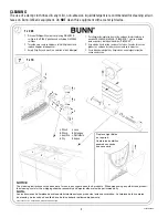
SERVICE (cont.)
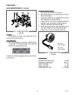
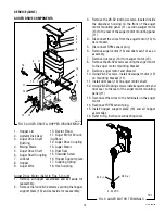
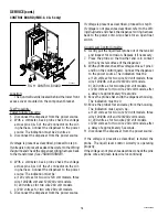
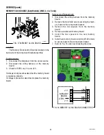
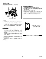
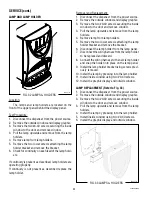
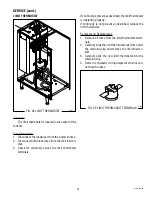
CONTROL BOARD (IMIX-3, 4 & 5 only)
FIG. 11 CONTROL BOARD
P3250.25
Location:
The Control Board is located behind the lower front
access cover mounted on the component bracket.
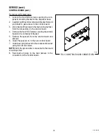
Test Procedure:
Power Supply Circuitry:
1. Disconnect the dispenser from the power source.
2. With a voltmeter, back probe check the voltage
across pins 4 & 5 of the J2 connector on the wir-
ing harness. Connect the dispenser to the power
source. The indication must be 24 volts ac.
3. Disconnect the dispenser from the power source.
If voltage is present as described, proceed to step 4.
If voltage is not present as described, refer to the
Wiring
Diagrams
and check the dispenser wiring harness back
to the transformer (See
TRANSFORMER
).
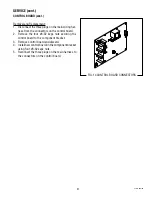
4. With a voltmeter, back probe check the voltage
across pins 3 & 4 of the J1 connector on the wir-
ing harness. Connect the dispenser to the power
source. The indication must be:
a) 120 volts ac for two wire 120 volt models, three
wire 120/208 volt and 120/240 volt models.
b) 240 volts ac for two wire 240 volt models.
c) 230 volts ac for two wire 230 volt models.
5. Disconnect the dispenser from the power source.
If voltage is present as described, proceed to step 9.
If voltage is not present as described, refer to the
Wir-
ing Diagrams
and check the dispenser wiring harness
back to the power cord. Also check for an open float
switch.
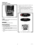
Liquid Level Control Circuitry:
6. Gently pull the liquid level probe out of the tank lid
and inspect for corrosion. Replace it if necessary.
7. Place the probe so that neither end is in contact
with any metal surface of the dispenser.
8. With a voltmeter, check the voltage across J1 pins 4
and 8 on the control board. Connect the dispenser
to the power source. The indication must be:
a) 120 volts ac for two wire 120 volt models, three
wire 120/208 volt and 120/240 volt models,
b) 240 volts ac for two wire 240 volt models,
c) 230 volts ac for two wire 230 volt models, after
a delay of approximately 10 seconds.
9. Move the probe’s flat end to the dispenser housing.
The indication must be 0.
10. Move the probe’s flat end away from the housing.
The indication must, again, be:
a) 120 volts ac for two wire 120 volt models, three
wire 120/208 volt and 120/240 volt models,
b) 240 volts ac for two wire 240 volt models,
c) 230 volts ac for two wire 230 volt models, after
a delay of approximately 5 seconds.
11. Disconnect the dispenser from the power source.
If the voltage is present as described, re-install the
probe. The liquid level control circuitry is operating
properly.
If the voltage is not present as described, check the pink
probe wire and green tank wire for continuity.
42032 060109
Summary of Contents for IMIX
Page 10: ...10 42032 060109 NOTES ...
Page 46: ...46 42032 060109 ...
Page 48: ...48 42032 060109 ...


