


26
P1449
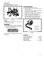
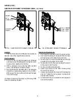
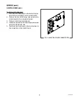
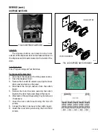
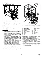
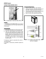
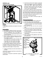
FIG. 22 DISPENSE SWITCH TERMINALS
Station #1
Station #2
Station #3
BLK
ORN
BLK
RED
BLK
TAN
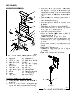
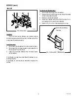
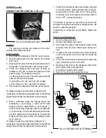
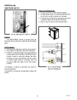
DISPENSE SWITCHES (IMIX-3S+ & 5S+ only)
P3645
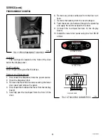
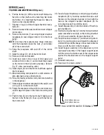
SERVICE (cont.)
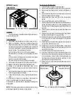
Location:
The dispense switches are located on the lower
outside of the dispenser door.
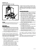
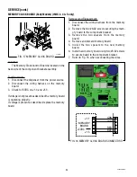
Test Procedure:
1. Disconnect the dispenser from the power source.
2. Open the dispenser door and remove the bottom
door cover.
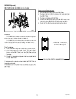
3. Disconnect the wires from the door interconnect wir-
ing harness to the dispense switch to be tested.
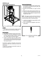
4. Check for voltage across each pair of wires as
indicated in Fig. 26. Connect the dispenser to the
power supply. The indication must be:
a) 120 volts ac for two wire 120 volt models, 120/208
volt and 120/240 volt models.
b) 240 volts ac for two wire 240 volt models.
c) 230 volts ac for two wire 230 volt models.
5. Disconnect the dispenser from the power source.
If voltage is present as described, proceed to #6.
If voltage is not present as described, refer to the
Wiring
Diagrams
and check the dispenser wiring harness.
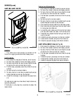
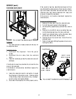
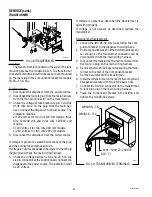
6. With a voltmeter, check the voltage across the
blue/black (+) and orange (-) wires for the right
dispense switch, black/white (+) and orange (-)
wires for the center dispense switch, or blue/white
(+) and orange (-) for the left dispense switch from
the door interconnect wiring harness. Connect the
dispenser to the power source. The indication must
be +5 volts dc.
If voltage is present as described, proceed to #7.
If voltage is not present as described, refer to the
Wiring
Diagrams
and check the dispenser wiring harness.
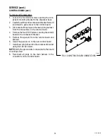
7. Check for continuity across the terminals (top right
to top left; bottom right to bottom left) of the dis-
pense switch with the switch in the “ON” position.
Continuity must not be present when the switch is
in the “OFF” (released) position.
If continuity is present as described, reconnect the
connector to the door interconnect wiring harness, the
switch is operating properly.
If continuity is not present as described, replace the
switch.
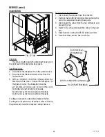
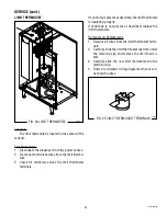
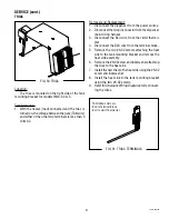
Removal and Replacement:
1. Open the dispenser door.
2. Remove the bottom door cover.
3. Disconnect the wires on the dispense switch to be
removed from the door interconnect wiring har-
ness.
4. Compress the clips inside the door on the dispense
switch and gently push the switch through the
opening.
5. Push new switch into the opening and spread the
clips to hold the switch in the door.
6. Reconnect the wires to the dispense switch from
door interconnect wiring harness.
7. Reinstall the bottom door bottom.
8. Refer to Fig. 22 when reinstalling wires.
FIG.21 DISPENSE SWITCHES
42032 060109
Station #4
Station #5
BLK
GRN
BLK
YEL
Summary of Contents for IMIX
Page 10: ...10 42032 060109 NOTES ...
Page 46: ...46 42032 060109 ...
Page 48: ...48 42032 060109 ...