GAS 222.20 Ex1
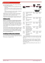
4.7.2 Connecting the Heating Tape
The probes have a self-regulating heating tape which con-
nects inside the junction box per the terminal designations
inside the terminal box. To ensure the highest level of safety
possible (preventing fires, etc.) the manufacturer of the heat-
ing tape requires using RCDs of at least 30 mA. Further use a
circuit breaker for adequate protection.
• Regularly check the function of the electrical protection.
• Also check visible parts of the heating tape for damage,
e.g. from transport. Damaged heating tapes may allow
moisture and dirt to enter and result in arcing and a heat-
ing system fire. Damaged heating tapes must not be
used. Regularly check the visible area of the heating tape
for mechanical damage during operation (visual inspec-
tion).
• Also observe the applicable explosion protection regula-
tions when connecting the heating system to power. The
manufacturer of the heating tape recommends regularly
measuring the insulation resistance of the heating tape.
The insulation resistance must be measured between the
short-circuited copper conductors and the protective
braiding. Measure with an insulation tester at a test
voltage of 2500 VDC. The insulation resistance should be
at least 10 MOhm.
On probes purchased with solenoid valves these will be fact-
ory fitted to the terminal strip.
Inside the junction box (pin assignment see drawing in the
appendix) are terminals for connecting the solenoid valves for
automatic blowback.
5 Operation and Control
NOTICE
The device must not be operated beyond its specifications.
NOTICE
The weather hood must be closed during operation!
DANGER
Explosion hazard due to electrostatic discharge
Equipment may only be used where normal operating condi-
tions do not produce frequent flammable, electrostatic dis-
charge.
5.1 Before Startup
Before starting the device, verify:
• The hose and electrical connections and the heating tape
are not damaged and installed correctly.
• No parts of the sample gas probe have been removed.
• The protection and monitoring devices are installed and
functional (e.g. flame arrester).
• The gas inlet and outlet on the gas probe are open.
• Ambient parameters are met.
• Probe parts are resistant to media to be conveyed and in
the surrounding area.
• The performance specifications in the type plate are met.
• The voltage and frequency of the heating tape match the
mains values.
• The electrical connections are tight.
• The monitoring equipment is connected and set as spe-
cified.
• Precautions have been taken.
• The earth is proper and functional.
• The downstream filter and the handle with O-ring are in-
stalled (if applicable).
6 Maintenance
Always observe the applicable safety- and operating regula-
tions when performing any type of maintenance. Please refer
to the original operator’s manual on the included CD or online
at www.buehler-technologies.com for maintenance informa-
tion.
7 Service and Repair
Please refer to the original operator’s manual on the included
CD or online at www.buehler-technologies.com for a detailed
description of the unit including information on
troubleshooting and repair.
15
Bühler Technologies GmbH
BX460041 ◦ 03/2021


