background image

Description

2

CLS Pro 600 – Line and Contrast Sensor 

17/108

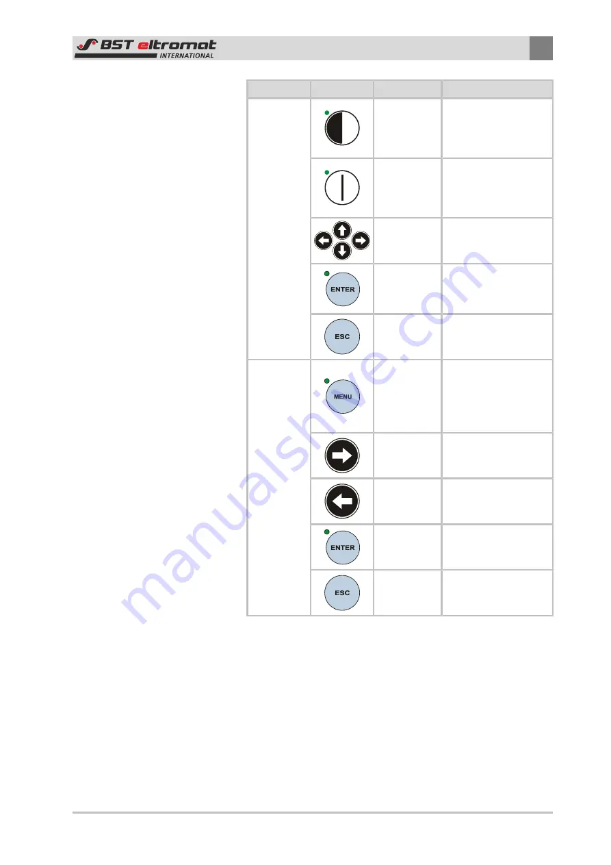
Function

Key

Designation

Description

Setup

Mode

Edge SETUP

Calls up the edge guid-
ing setup mode (only
possible in 

MAN

mode)

Line SETUP

Calls up the line guid-
ing set-up mode (only
possible in 

MAN

mode)

Arrow Keys

Used to enter settings
as shown in the oper-
ating help page

ENTER

Imports the mode /
parameter settings

Exit the Setup mode

ESC

Aborts the parameter
entering process

Menu

MENU

Calls up or exits the
quick menus (the key
must be held down for
at least 3 seconds to
call up the menu)

Right Arrow
Key

Used to enters a sub-
menu or parameter

Left Arrow
Key

Pages back by one
menu level (does not
exit the menu)

ENTER

Used to open a sub-
menu or select a para-
meter

ESC

Pages back by one
menu level and might
also close the menu

2.6

Safety Information

The  safety  relevant  information  in  accordance  with  DIN  EN  ISO
13857,  DIN  EN  349  and  the  industry  specific  accident  prevention
regulations  must  always  be  taken  into  consideration  when  in-
stalling  the  BST-eltromat  equipment  in  the  production  machine,
these include:

There  must  always  be  a  safe  distance  between  the  BST-eltro-
mat  equipment  and  the  machinery  already  installed  on-site,
such as machine panels, building structures, etc.

Summary of Contents for CLS Pro 600

Page 1: ...Web Guiding System Installation and Operating Manual CLS Pro 600 Line and Contrast Sensor MD 323 EN 08 Translation of the Original Manual ...

Page 2: ...E Mail info bst international com Internet www bst eltromat com This documentation is protected by copyright The translation as well as reproduction and distribution in any form is forbidden without the approval of the rights holder and will be pursued under civil and criminal law Technical modifications reserved ...

Page 3: ...5 2 5 Control Panel 16 2 5 1 Graphic Display 16 2 5 2 Control Panel 16 2 6 Safety Information 17 2 7 Laser 19 2 8 Emissions 19 3 Assembly 20 3 1 Installation Site Requirements 20 3 2 Sensor Installation 20 3 2 1 General Information 20 3 2 2 Sensor with supplied holder 20 3 2 3 Installing the Sensor Using a Holder Supplied by the Customer 21 3 2 4 Setting the Gap Between the Sensor and the Sensing ...

Page 4: ...Activating Line Setup Edge Setup 51 6 5 Standard Operation 51 6 5 1 Selecting a Job 51 6 5 2 Edge Setup Mode 52 6 5 3 Line Setup Mode 54 6 6 Extended Operation 56 6 6 1 Change User 56 6 6 2 Job Administration 57 6 6 3 Assigning User Levels to the Parameters 58 6 6 4 Setting up Quick Menus 59 6 6 5 Setup Administration 60 6 7 Main Menu Parameter Meanings 61 6 7 1 Configuration 61 6 7 2 Parameter 68...

Page 5: ... Storage 91 12 Decommissioning 92 Index 93 A Appendix 1 Commissioning as a Stand Alone System 95 A1 Blockage 95 A2 Control Signal 95 A3 Commissioning 95 A4 Configuring the Guiding Block Output 96 A5 Defining the Mounting Position 97 B Appendix 2 Saving Parameters and Loading Firmware 98 B1 Save Parameters 98 B2 Loading Firmware 98 B2 1 Loading Sensor Firmware 99 B2 2 Loading Panel Firmware 99 C Ap...

Page 6: ...st also be familiar with these instructions 1 3 Storage and Distribution These instructions must be stored at the workplace in such a man ner that the user has access to them at all times These instructions and all other applicable documents are a com ponent of the product and must be handed over to the operating company of the system 1 4 Meanings of the Safety Instructions and Symbols 1 4 1 Safet...

Page 7: ...ons And 2 in the sequence specified Requirement for you to take actions without any certain se quence 1 4 3 Operation Using Keys Operations using the keys are indicated by the following symbols Press key Press key or key Press key and key at the same time 1 5 More Detailed Information Observe the accompanying documents e g order confirma tion for this system and the operating instructions of the e...

Page 8: ...rmware of this sensor Ignoring this warning might result in the warranty rights being invalidated The settings and details shown in this operating manual e g in the display screens are given as examples only unless the text ex plicitly states otherwise The latest version of the operating manual for the CLS Pro 600line and contrast sensor can be obtained via the Internet in all avail able languages...

Page 9: ... are to be used for this Spare parts obtained from third parties cannot be guaranteed to comply with the design and manufacturing con ditions and safety regulations In this case any guarantee claims made against the BST eltromat web guiding system will be invalid ated Only qualified personnel who have been trained on the sys tem are allowed to undertake any work required on the BST eltro mat web g...

Page 10: ...ICE Please note The length of the connection cable between the sensor and the control panel must never exceed 20 m maximum 2 3 2 Functional Principle The sensor records the actual position of a line or a contrast trans ition point on the material web in automatic mode and then trans mits the relevant information to the interconnected controller The controller compares the actual recorded position ...

Page 11: ... controller Customer s machine controller Sensor CLS Pro 600 with control panel BST eltromat Signal Terminal Box1 optional CAN bus connection optional Fig 4 Application with ekrPro Com60 controller Application with ekr 500 digital controller Customer s machine controller Sensor CLS Pro 600 with control panel BST eltromat Signal Terminal Box1 optional CAN bus connection optional Fig 5 Application w...

Page 12: ...control panel from software version 1 8 1 CAN Module bus coupler EKR 1500 CCD Line Guider Fig 6 Application with EKR 1500 CCD line guider as CCD 2004 replacement 2 4 Terms Used in this Manual 2 4 1 General Information In principle the windows displayed on the keyboard s graphics display are laid out as follows Fig 7 Display Layout Status Bar Footer ...

Page 13: ...transfer point posi tion in the sensor scanning area It can be set up in Automatic mode using the control panel s arrow keys see Chapter 6 3 2 The set point position will be indicated by a white triangledis played on the control panel s screen Fig 8 SET POINT Position without deviation Center of Measuring Range Contrast Quality graphical Standard SET Position The deviation will be faded in as plai...

Page 14: ...r of Measuring Range The contrast quality will be graphically displayed in the bottom section of the window 2 4 3 Measuring Range The sensor s measuring range is 25 x 3 mm W x H Fig 10 Measuring Range 2 4 4 Search Area The search area is a section within the measuring area The line edge that has to be evaluated and controlled afterwards is located in this section ...

Page 15: ...er This tells you when op timisations can be implemented in the displayed window or what the actual setting of the selected parameter is and how it can be configured 2 4 7 First Edge Second Edge The edge that will be controlled afterwards can be defined for the line scanning process First Edge and Second Edge are both avail able for use as options The edge position on the left of the display must ...

Page 16: ...on the control panel s screen during operation The meaning of the individual symbols is described in chapter 6 2 2 5 2 Control Panel Three different groups of keys are integrated in the control panel and they have the following functions SETUP Keys Used to select setup mode Blue Keys Used to access the menu import the parameters or exit the parameter enter ing process Arrow Keys Used to enter sett...

Page 17: ... 3 seconds to call up the menu Right Arrow Key Used to enters a sub menu or parameter Left Arrow Key Pages back by one menu level does not exit the menu ENTER Used to open a sub menu or select a para meter ESC Pages back by one menu level and might also close the menu 2 6 Safety Information The safety relevant information in accordance with DIN EN ISO 13857 DIN EN 349 and the industry specific acc...

Page 18: ...fety devices that were attached to the guiding device must be removed prior to commissioning NOTICE Please note Only trained specialist personnel are permitted to undertake the assembly installation and commissioning DANGER Danger of cuts Never touch the edges of running material webs DANGER Danger of crushing Never reach into the area in between the fixed lower frame and the guiding device s movi...

Page 19: ...ety concept of the production machine during commissioning 2 7 Laser CAUTION Please note A laser is used as a positioning aid when positioning the sensor This laser unit has been classified by the manufacturer as a Class 2 laser in compliance with DIN EN 60825 1 2001 11 This laser will not cause eye damage even after long radiation periods and even if other optical tools lenses etc are used in the...

Page 20: ...ING Sensor is not ATEX certified The sensor and the control panel have not been ATEX certified i e they are not approved for use in potentially explosive areas and must never be used in them 3 2 Sensor Installation 3 2 1 General Information This chapter describes the procedure for installing the sensors us ing the holders supplied in the package or the connection options available if using a holde...

Page 21: ...mer If the sensor has been supplied without a holder then the cus tomer must provide a relevant securing device Securing threads are available at the sensor enclosure for this purpose The connec tion sizes can be found in the following drawing Fig 14 Installing the Sensor Using a Holder Supplied by the Customer M6 7 deep securing threads for securing holder provided by customer on both sides ...

Page 22: ...sor enclosure s measuring window Slide the sensor along in the sensing roller direction until the pro tective packaging lies up against the sensing roller see drawing Pull the protective packaging out to one side afterwards Fig 15 Setting the Gap Between the Sensor and the Sensing Roller Sensor Enclosure Protective Packaging Scanning Roller 3 2 5 Turning the Control Panel The control panel can be ...

Page 23: ...ed correctly due to the existing installation situation The relevant procedure is de scribed in the following Fig 17 Fastening Screws Fastening Screws 1 Unscrew the four control panel fastening screws 2 Carefully pull the control panel upwards and away from the sensor 3 Turn the control panel into the required position see illustra tion above Fig 18 Cut out Cut out ...

Page 24: ...ensor 3 2 6 Rotating the Control Panel The control panel can be rotated on the supporting ring see drawing in chapter 2 3 1 Fig 19 Rotating the Control Panel 1 Therefore unscrew the control panel from the mounting plate and remove it After that loosen the fastening screws of the mounting plate Now rotate the mounting plate in the desired direction 2 Afterwards tighten the fastening screws again an...

Page 25: ...on The control panel is secured to a level surface Procedure See chapter 3 3 3 2 Console installation The control panel is installed in an existing on site control con sole or a control station Procedure See chapter 3 3 4 Please note A CLS Pro 600 securing kit which is available as an op tion is needed to install the control panel in a control console BST eltromat Order No 133 459 Cable Extension ...

Page 26: ...ng the Holder Sensor Enclosure Fastening Screws Holder 1 Unscrew the holder s securing screws in the enclosure 2 Pull out the holder 3 The next procedures depend on the type of installation Refer to section 3 3 3 for a wall mounting or section 3 3 4 for a con sole mounting ...

Page 27: ...27 108 3 3 3 Wall Mounting Securing Hole Diagram Fig 21 Control Panel Enclosure Preparations Fig 22 Unplug the connecting cable Control Panel Connecting Cable Plug X100 1 Unplug the plug of the control panel connecting cable from the sensor plug X100 ...

Page 28: ...e securing screws of the holder Fastening Screws Plug 2 Unscrew the holder s four securing screws from the sensor enclosure Fig 24 Remove holding ring and control panel Holding Ring 3 Pull the holding ring and control panel sideways out of the groove in the sensor enclosure ...

Page 29: ...e Control Panel Fastening Screws 4 Unscrew the four control panel securing screws and put them aside These screws will be needed for the wall mounting later on 5 Pull the control panel out of the mounting plate Now pull the connecting cable and the plug carefully through the cut out in the mounting plate ...

Page 30: ... holes as shown in the securing screw hole template 2 Use the four M3 screws to screw the control panel on The four hexagon screws that secured the control panel to the sensor when the unit was delivered can be used for this 3 Use the optional extension cable to connect the control panel to the sensor 4 Plug the extension cable connector into the sensor s X100 socket ...

Page 31: ...on Installation Cut Out Fig 27 Installation cut out Preparations Please note A securing kit which is available as an option is needed to install the control panel in a control console BST eltro mat Order No 133 459 Fig 28 Pull out the plug Control Panel Connecting Cable Plug X100 ...

Page 32: ...rol panel connecting cable from the sensor plug X100 Fig 29 Unscrew the securing screws Fastening Screws Plug 2 Unscrew the four control panel securing screws and put them aside These screws will be needed for the console mounting later on Fig 30 Take off the control panel ...

Page 33: ...31 Installing the control panel Threaded Pins Securing Plates 1 Cut out the section 2 Carefully push the control panel into the cut out section 3 Use two of the securing screws to screw the two securing plates part of the installation kit onto the back of the control panel The four hexagon screws that secured the control panel to the sensor when the unit was delivered can be used for this Fig 32 T...

Page 34: ...sor 4 Screw the four threaded pins into the securing plates until the control panel is held firmly in place 5 Use the optional extension cable to connect the control panel to the sensor 6 Plug the extension cable connector into the sensor s X100 socket ...

Page 35: ...he securing screws in the plugs 3 Ensure that the voltage supply has the correct potential equal isation in accordance with the local regulations 4 2 Sensor 4 2 1 Enclosure Sockets Fig 33 Connections Enclosure plug socket Function Remark x100 Control panel connection Plug x101 Controller Connection Socket x80 I O Connection optional Terminal Box BST eltro mat STB 1 connection box with terminal str...

Page 36: ...signation Meaning H1 RUN OFF STOPPED The unit is in the initialization phase No data transfer can take place FLASHING PREOPERATIONAL The device is in PREOPERATIONAL mode The initialisation process is complete The device can be started ON OPERATIONAL The unit is in OPERATIONAL mode H2 ERR OFF NO ERROR The device is functioning properly There is no error present FLASHES 3x SYNC ERROR No SYNC message...

Page 37: ...4 4 Setting the DIL Switches The S4 DIL switch is used for making application specific settings DIL Switch Meaning S4 1 Not used at the moment S4 2 Not used at the moment S4 3 Not used at the moment S4 4 ON Sets the sensor up as a stand alone system In this case the sensor is used as the NMT master and bus system sync generator S4 4 OFF Set up the sensor to work with ekrPro Com60 ekr 500 Plus ekr ...

Page 38: ...ate application The following information window will be superimposed on the screen if the panel cannot make bus contract with the sensor The following are displayed The panel s node number on the bus Commander Node The synchronization status SYNC The module status Modulstate Whether the sensor has been detected on the bus Sensor at Whether the terminator resistor has been set up Resistor There mu...

Page 39: ... parameters for the material and define the guiding mode line edge 5 1 2 Input Options Entries must be made in different sections of the menus select the entries from the options list or activate the functions The changes are made as follows Direct via the entry screen The positions that have to be changed will flash Or In the footer The selected parameter is displayed showing the current setting ...

Page 40: ...The entry must now be made as described above Option List An entry from a default list can be selected from an option list Example 1 Select the required parameter 2 Confirm the selection by pressing ENTER This will open up the settings window 3 Use the up down arrow keys to scroll through the entries dis played in the list Press ENTER to confirm the selected entry The entry will be imported Checkb...

Page 41: ...ntry General Information The separate menu section descriptions assumes that the menu has already been called up Opening the menu will only be displayed once Follow this proced ure before you start to edit the specific parameters 1 Hold the MENU key on the panel down for at least 3 seconds 2 The main menu will be displayed in the footnote at the bottom of the screen Select the enter m entry here w...

Page 42: ...e and Contrast Sensor 1 Log on as Admin 2 Open the main menu first 3 Now select the configuration sub menu 4 Select sensor and then open the setting up window ð The path details will then be displayed in the description configuration sensor ...

Page 43: ...word level operator Section 6 7 5 Access password level operator Fig 35 Menu Structure Access to the different menus and sub menus depends on the as signment to the password levels You will find the assignment according to the factory default set tings in appendix A3 You can adapt those assignments The pro cedure is described in section 6 6 3 Explanations for the specific menu sections can be foun...

Page 44: ...kr 500 Plus ekr 500 digital See Quick Reference Guide Web guiding system ekr 500 Plus digital with CLS Pro 600 MD 341 01 xx 5 2 3 EKR 1500 CCD Line Guider and C2M Coupler See Quick Reference Guide Web guiding system EKR 1500 with CLS Pro 600 and C2M module MD 351 01 xx ...

Page 45: ...onent optimisation is required Parameter settings might have to be remade Optimising the specific parameters and their significance are described in Section 6 6 Expanded operation 6 2 Operating Display The CLS Pro 600 screen display depends on the mode that the sensor will be working in We differentiate between setup mode and scanning mode The menu can be called up from either mode However access ...

Page 46: ...lity details Possible Contrasts Contrast quality of the edges lines ly ing in the searched area graphically displayed Operating Help Operating help has been integrated in the footer This shows you how the optimisation can be run in the displayed window Pre select the Setup Functions by using the up down ar row keys Activated in the standard settings are Move search area and Change size of search a...

Page 47: ...line and displays the standard set point Contrast Contrast quality of the tested edge line is graph ically displayed Operating Help Operating help has been integrated in the footer This shows you how the optimisation can be run in the displayed window Pre selects the ekrPro Com60 mode and other remote con trol functions Set Point Adjustment W in AUTO mode Move guiding device left right mot in MAN ...

Page 48: ...mode Sensor in setup mode Sensor in stand alone mode Sensor transmitting an interlock Sensor has not detected a valid edge Controller has activated Watchdog edge 1 Controller has activated Watchdog edge 2 Controller is in manual mode Controller is in automatic mode System is in servo center position SC mode No controller detected on the bus 6 3 Remote Control of ekrPro Com60 ekr 500 Plus ekr 500 d...

Page 49: ... the screen The sensor will switch over to the operating mode Manual 6 3 2 Automatic Automatic material web controlling is carried out in this mode de pending on the scanning mode that was selected edge or line 1 Use the up or down arrow keys to select operating mode Automatic The selected mode will be displayed with a green border around it 2 Press ENTER to confirm your selection 3 The current mo...

Page 50: ...enter position 6 3 4 Moving the Set Point Position W value Use the left right arrow keys in automatic mode to adjust the set point 6 3 5 Moving the Guiding Device Use the left right arrow keys in manual mode to move the guiding device to the left or right 6 3 6 Setting the Controller Gain You must be logged on as Admin The controller gain can be reset via the configuration re mote control ekr gain...

Page 51: ... necessary basic settings will be implemented when the required job is selected You only have to enter the necessary set up edge or line for the work The system is now ready for operation 6 5 1 Selecting a Job Jobs are loaded via the parameter jobs choose job load job menu The following selection window will be displayed You can select between the jobs entered in the factory here Job Name Meaning ...

Page 52: ... your own jobs The procedure is described in Section 6 6 2 If you have changed over to setup mode or if the set up line or set up edge keys are pressed again in setup mode then the cur rently loaded job will be displayed on the screen for 2 seconds If it is not displayed then the system will be operated using the machine default values or manual modified parameters which have not been assigned to ...

Page 53: ...red Press the ENTER button The LEDs inside the ENTER and SETUP keys will be extin guished The display will change over from setup mode to scan ning mode 7 If edge K2 has to be used for the guiding then the arrow keys must be used to define the search area In this case you must select define search area and set up the size of the search area accordingly Press the ENTER button The LEDs inside the EN...

Page 54: ...switched on and it will flash The laser is switched on and the laser line will be visible simultaneously Fig 39 Line Setup Mode 4 Use the laser line to position the camera on the required line 5 Use the mechanical adjustment device to fix it in position The line with the best contrast will be selected automatically by the system In this case it is line L1 6 If the automatically pre selected line i...

Page 55: ... present as shown in the example then the displayed pre selection will be used for the standard settings This can result in the controller producing unclean web guiding due to the unevenness of LK1 The Area Tracking will have to be used in this case Only one edge LK2 will be tracked but this will be compared by checking the color of an area alongside the edge This will enable the noise spikes to b...

Page 56: ...must be entered in setup mode The meanings of the specific parameters are described in the fol lowing 6 6 1 Change User Use this parameter to assign or change the user level in a dialog window Different setting up options are available but they de pend on the user level Which parameter a user can adapt and which functions he can use are defined in the configuration menu see Configuration section A...

Page 57: ...onsisting of material and or job specific parameters can be saved as a Job These jobs can be called up whenever necessary This enables you to set up repeat jobs quickly and without any errors Certain basic jobs have already been pre configured in the factory and are avail able under the parameter jobs choose job load job menu see Section 6 5 1 as well Saving a Job Proceed as follows if you want to...

Page 58: ...lled up in setup mode and you have to be logged on as Admin A relevant information window will be opened up if you try to call it up from scanning mode see screenshot on the left Procedure Call up the configuration edit menu configuration sub menu The dialog window is sub divided into the following sec tions Parameter Display Assigned User Levels Footer with User Help ð Only the parameters that th...

Page 59: ...the quick menu or not Footer with User Help ð Only the parameters that the current user hold access rights to will be displayed in the parameter screen Assignments 1 Use the up down arrow keys to select the parameter that you want to optimise and then press ENTER to confirm your selec tion 2 The associated editing window will be opened The time ms parameter window is used as an example here 3 Now ...

Page 60: ...e recognised by the designation used following the name of the respective slot 4 Press ENTER to confirm your entry The setup is saved to the selected slot know 5 If you have selected a slot that is already in use the warning message file exists is displayed If you actually want to over write this slot press ENTER know If you do not desire to over write the slot please cancel this procedure by pres...

Page 61: ...be deleted using the arrow keys 3 Press ENTER to confirm your selection The warning message delete slot is displayed know If you actually want to delete this slot press ENTER again If you do not want to delete the slot press ESC to cancel this procedure 6 7 Main Menu Parameter Meanings 6 7 1 Configuration The sensor panel and mounting position settings are entered via the Configuration sub menu Ca...

Page 62: ... edge This gives you the option of selecting a rear edge for line scanning The right edge limit will flash red You can select any other edge that is found enable alternative line This gives you the option of selecting an al ternative line Both edge limits will flash red You can select any other line that is found hide menu If the parameter is active you can call up the main menu by holding down th...

Page 63: ...ial will not be moved keep value The setting will not be changed automatically when you exit setup The material will not be moved Pre Adjustment keep value active USB Activates the memory function The panel s configuration data can also be accessed via the USB interface and this data can also be saved externally if necessary Furthermore this also gives you the option of loading firm ware updates P...

Page 64: ... white balance will be dis played in an information window 4 Now press the ENTER key to exit the white balance process guiding lock delay Use this parameter to set up how long the last measured value must be retained for un til a blocking signal is sent This will ensure that a minimum control time is run when scanning a broken line and that the guiding device can react Setting Range 0 9999 ms Defa...

Page 65: ... the edge that will be used for the controlling This para meter is only available for line scanning ap plications Setting Options median of 1 and 2 Standard setting A median value will be cre ated using both edges of the line and this will be generated as the control position first edge It will be controlled by the left edge as dis played on the screen second edge It will be controlled by the seco...

Page 66: ...t made each time a key is pressed is defined by this parameter If an arrow key is kept held down for 350 ms then a new 150 ms adjustment step will be introduced automatically If the arrow key is kept held down for longer than the time defined in the time to increase step width parameter it will switch over to the adjust ment step width defined in the fast step width of guiding position parameter S...

Page 67: ...efined in this sub menu and the different configurations are also set up here Parameter Function Meaning select Use the select parameter to select a pre con figured mounting position You can select from 4 different mounting positions in prin ciple but mounting position A is the stand ard setting and mounting positions B D are optional and these must be activated before you can use them configurati...

Page 68: ... detailed descriptions 6 7 2 Parameter The parameters that apply to the measuring process are as sembled in this section of the main menu Meanings and procedures for the individual settings are described below 6 7 2 1 parameter jobs jobs The job administration procedure is described in detail in Section 6 6 2 6 7 2 2 parameter illumination illumination The parameters that apply to the lighting are...

Page 69: ...ing Options ON OFF Pre Adjustment ON The optional and external parameters are not used at the mo ment 6 7 2 3 parameter destination destination Use this parameter to set up over or underexposure for the relev ant area in automatic mode These settings can also be used for weak colors inside a light background Setting Range 0 300 Pre Adjustment 100 i e no overexposure 6 7 2 4 parameter contrast dete...

Page 70: ...gh contrast scratches etc A smaller value can be set up if very small lines are de tected reliably Settings 0 1 0 2 0 3 0 4 0 5 mm Default Setting 0 3 mm 6 7 2 5 parameter contrast tracking contrast tracking The tracking conditions for exceptional materials are optimized in this sub menu e g poor contrast or print edges with different col ors 6 7 2 6 parameter plausibility check plausibility check...

Page 71: ...ecked Setting Options all color checks the right side the left side and the line off no color checks only left side color checks run on the left side only only right side color checks run on the right side only only line only the line color will be checked only not line color checks the right side and the left side but not the line Pre Adjustment only line line intensity This parameter defines the...

Page 72: ... edge scanning If the function is switched then blocking will be released again after an inter ruption when the gap corresponds to is lar ger than or is missing when compared to be forehand If a contrast that lies closer to the contrast being scanned is detected blocking will remain in place Setting Options ON OFF Pre Adjustment ON contrast quality Use this parameter to define whether the contrast...

Page 73: ... 256 values last value new value 256 color This parameter defines whether the color comparison value should be guided Setting Options ON OFF Pre Adjustment ON contrast This parameter defines whether the search contrast threshold should be guided NOTICE This parameter is only active if contrast detection auto adjustment is switched on Setting Options ON OFF Pre Adjustment ON edge sharpness This par...

Page 74: ...d the next is big then the parameter must be set up more precisely in order to prevent the system jumping to a wrong edge line Setting Range 1 8 mm Pre Adjustment 2 mm 6 7 2 9 parameter line width tolerance line width tolerance Use this parameter to define the tolerance with which the line be ing checked will be seen as a valid line The line width can only de viate from the reference by the value ...

Page 75: ...k value applies Small value for broken lines Big value for a splice Setting Range 0 001 10 000 Pre Adjustment 0 01 6 7 2 12 parameter web stop detection web stop detection Use this parameter to switch the automatic web movement de tection on and off If this function is switched on then web move ment will be checked if the edge was lost The search area will be only be opened if web movement has bee...

Page 76: ...e displayed on the panel s screen in several different ways The display sub menu is used to configure the signal display You can select the type of display from here You can select from the followings display settings Extended contrastview default RGB R G B This display mode is essentially for service purposes and is used by BST eltromat for evaluating the sensor conditions ...

Page 77: ... System Info General system information is displayed in the System Info sub menu You need this information to identify the equipment e g when requesting support from BST eltromat service The following pages will be displayed after you have called up this sub menu ...

Page 78: ...r or operator panel processes occur or re occur after the devices have been changed 7 1 1 Sensor Device Address The sensor device address was preset to 1 in the factory deliv ery state Caution You are only allowed to modify the device address if au thorized to do so by the manufacturer The sensor s device address is set up using the S1 rotary switch The current setting is displayed in the System i...

Page 79: ... Panel Device Address The control panel s device address is set up using the S1 rotary switch fitted on the panel board The S1 rotary switch is mounted behind stopper B on the back of the control panel Fig 41 Setting the devicev address Switch Position Address 0 reserved 1 111 2 112 3 113 4 114 5 115 6 116 7 117 8 118 9 reserved The control panel s device address was preset to 1 in the factory del...

Page 80: ... the control panel connecting cable to the sensor 7 2 Terminator Resistors The internal terminator resistors for the sensor and the control panel were switched on in the factory The settings usually do not have to be modified Check the terminator resistor settings if mal functions or non defined sensor or operator panel processes oc cur or re occur after the devices have been changed 7 2 1 Sensor ...

Page 81: ...ition if necessary 5 Screw the stopper back into the sensor enclosure 6 Switch on the mains voltage 7 2 2 Control Panel Terminator Resistor The control panel s internal terminator resistor is switched on or off using switch S3 The current setting is displayed in the System info sub menu as Can Resistor Commander see Section 6 7 5 The S3 switch is mounted behind stopper C on the back of the control...

Page 82: ...the ON position if necessary 5 Replace the stopper 6 Reconnect the control panel connecting cable to the sensor 7 3 Restoring Factory Default Settings Caution The Configuration sub menu can only be called up in setup mode and you have to be logged on as Admin NOTICE Caution All of the settings made during operation will be overwritten when the factory default settings are reset configuration selec...

Page 83: ... of the line The sensor settings are not suitable for the job Maybe the wrong job has been loaded Load the job DEFAULT 4 After replacing the controller all indicators on the sensor display flash The frame of the display is grey and the tool key is shown in setup mode Wrong sensor software Install correct sensor soft ware 5 ekrPro Com60 with CLS Pro 600 In automatic mode the blocking signal lock ap...

Page 84: ...uding ripple Power Consumption max 0 5 A including panel 2 x lights 100 switched on and 80 mA external outputs 9 1 3 Digital Inputs 2 x digital inputs with metallic separation for path cycle reset Input Resistance 4 7 kOhm each Switching Threshold 4V low 8V high switch ing sensor can be used for only pnp 9 1 4 Digital Outputs 1x error output switched against 24V 1x external light switched against ...

Page 85: ...e us ing a 4 pin micro style M8 con nector 9 1 8 Weight Dimensions Weight Approx 1 18 kgs sensor without control panel and holder Dimensions See chapter 9 2 5 9 2 Control Panel 9 2 1 Environmental Conditions Working Temperature 0 45 C Storage Temperature 10 C 70 C Working Humidity 5 90 not condensing Protection Type IP 50 9 2 2 Power Supply Voltage 24V DC power supplied by the sensor 9 2 3 Display...

Page 86: ...iew A Fig 43 Sensor with mounted control panel and holder Material Web Scanning Roller Scan Point Fig 44 Sensor with holder but without control panel 1 The details refer to the use of a 25x25 mm square bar The adapter is not needed if a 35x35 mm square bar is used 2 Gap when using a 25x25 mm square bar 3 Gap when using a 35x35 mm square bar 4 Sensor offset by 180 ...

Page 87: ... customer See Section 3 2 3 for the connection dimensions min 165 mm space needed to swivel the panel Fig 45 Sensor with mounted control panel but without holder Holder must be provided by the customer See Section 3 2 3 for the connection dimensions Material Web Scan Point Scanning Roller Customer s Holder Measuring Range Laser Position Securing points for customer s holder on both sides Fig 46 Se...

Page 88: ...100 Control Panel Connector male View X Fig 48 Contact assignment of the X100 plug connector Contact Signal Remark 1 24 V 24 V Power Supply 2 CAN_H CAN Bus 3 GND Power Supply Ground 4 CAN_L CAN Bus Plug X101 Controller Connection View X Socket female Fig 49 Contact assignment of the X101 plug connector Contact Signal Remark 1 24 V 24 V Power Supply 2 CAN_H CAN Bus 3 GND Power Supply Ground 4 CAN_L...

Page 89: ...0 plug connector Contact Function Remark 1 GND Ground for Contact 2 and Contact 3 2 DOUT 24 V Output 3 LAMP_PLUS External Lighting 24 V Output 4 LAMP_TRIG External Lighting Trigger O P 12V 5 mA 5 ANALOG_OUT Analog O P 0 10 V 6 EXT_GND Insulated Ground for Contact 7 and Contact 8 7 EXT_GEAR External Synchronization Cycle 8 EXT_RESET External Synchronization Reset ...

Page 90: ...ngly In principle cable connections can only be disconnected after the sensor itself has been disconnected from the power supply Any guarantee claims will be invalidated if this instruction is ignored 10 2 Sensor The sensor is classified as an optical instrument It must be looked after accordingly The cleaning of the casing should be carried out with a dry clean and soft cloth The measuring window...

Page 91: ...lular lining material The unit must only be transported when it is packed in the original BST eltromat transport packing BST eltromat International GmbH will not be liable for damage to the sensor or control panel caused by incorrect transport packaging 11 2 Storage If the sensor and the control panel have been shipped as indi vidual parts and will not be installed immediately they must be stored ...

Page 92: ...edures must be prepared by the manufacturer of the machine You must take into consideration that the edge and line contrast sensor is gener ally considered to be an electrical electronic device which must be disposed of in accordance with the current legal requirements You may also be able to return the system to BST eltromat Inter national GmbH The corresponding agreement must be made first ...

Page 93: ...it 31 Securing set 25 Setting the device address 79 Technical data 85 Terminator resistor 81 Turning the control panel 22 Wall installation 25 Wall mounting 27 Weight 85 D Decommissioning 92 Device addresses 78 DIL switches DIL switch S4 37 Settings for stand alone system 37 Settings for use with ekrPro Com60 37 Display 85 Scan mode 47 Setup mode 45 E EMC suitable wiring 105 Emissions 19 Environme...

Page 94: ... Explosive Areas 9 R Remote control Move the guiding device 50 Move the set point 50 S Safety Information 8 17 Saving a job 57 SC Mode 49 Search Area 14 Selecting a job 57 Sensor Analogue output 84 Control panel interface 85 Digital inputs 84 Digital outputs 84 Dismantling the BST eltromat holder 25 Enclosure socket 35 Environmental conditions 84 Installation 20 Installation with BST eltromat hold...

Page 95: ...n the other side Due to the technical tolerances of the component the centre of guiding is not precisely 5 V but can deviate This does not have any influence on the control precision Caution In the event of a guiding block the analogue output signal must not be utilized for the controller A3 Commissioning Connection via the BST eltromat Signal Terminal Box 1 is required for stand alone operation T...

Page 96: ...u after you have completed these settings Now log on as Operator here 6 Commissioning the sensor as a stand alone system is now com plete 7 Exit the setup A4 Configuring the Guiding Block Output 1 Log in as an Admin in order to configure the guiding block out put see point 6 6 1 2 Then call up the path configuration sensor on the menu The following parameters are used to configure the guiding bloc...

Page 97: ...which signal will be transmitted from the digital output in the event of a guiding block 0 V guiding unlock preset 24 V guiding lock interlock activated Return to the Change User sub menu once you have finished configuring the settings Now log on again as Operator A5 Defining the Mounting Position The supporting teaching in process for the mounting position as described in the Quick Reference Guid...

Page 98: ... 3 Activate the sensor s memory function In this case you must press the function activation button The sensor will now be seen as another PC laptop drive 4 Copy the required data from the settings directory into a directory that you previously created for this purpose in the PC laptop 5 Call up the Safely remove hardware function from the task bar after you have saved the data and then cancel the...

Page 99: ... back into the sensor enclosure 7 Now run a sensor restart mains OFF ON The restart should take approx 40 seconds The firmware will be automatically loaded into the system during this time B2 2 Loading Panel Firmware 1 Unscrew the stop from the back of the panel that is fitted in front of the USB interface and then find the button that activates the memory function 2 Use a mini USB cable to connec...

Page 100: ...d hide menu Admin activated disable operat ing error dialog Admin activated sensor guiding mode Admin keep value active USB Admin white balance Admin adjust sensor Service guiding block delay ms Admin 20 dig Out reset delay ms Admin 0 dig Out set delay ms Admin 0 mode digital out Admin guiding edge Admin median of 1 and 2 remote control ekr internal W Val Admin deactivated enable remote control Ad...

Page 101: ...ed Admin deactivated B Guiding dir ection Admin deactivated B Remote con trol inv Admin deactivated B W Value control inv Admin deactivated config position C C enable Admin deactivated C Teach in Admin deactivated C Sensor in verted Admin deactivated C Guiding dir ection Admin deactivated C Remote con trol inv Admin deactivated C W Value control inv Admin deactivated config position D D enable Adm...

Page 102: ...d external Operator deactivated brightness Maintenance automatic Maintenance destination Maintenance 100 contrast detec tion quality Maintenance 45 auto adjust ment Maintenance activated min line width mm Maintenance 0 3 contrast track ing plausibility check edge color Operator All edge intensity Maintenance deactivated line color Maintenance deactivated line intensity Maintenance deactivated edge...

Page 103: ...ent Maintenance activated splice misalign ment mm Maintenance 3 line width toler ance mm Maintenance 0 1 position aver aging Maintenance deactivated recapture factor Maintenance 00 050 web stop detec tion Maintenance activated Remote Guiding Controller gain factor Xp 006 00 Display signal view type Maintenance extended con trast view System Info Operator ...

Page 104: ...ssignment of the Terminal Strip Ter minal Function Remark 1 GND Ground for Pin 2 and Pin 3 2 DOUT 24 V Output 3 LAMP_PLUS External lighting 24V output 4 LAMP_TRIG External lighting trigger O P 12V 5 mA 5 ANALOG_OUT Analog O P 0 10 V 6 EXT_GND Insulated ground for Pin 7 and Pin 8 7 EXT_GEAR External Synchronization Cycle 8 EXT_RESET External Synchronization Reset Installation NOTICE Caution Only qu...

Page 105: ...not sufficient due to its small diameter in order to overcome the contact force of the clamping springs the clamp must be correctly opened using a screwdriver Check that all the cables are fitted tightly after the connections have been made in both cases D1 Installation Instructions For EMC Wiring Figure Wiring step Unscrew the union nut on the cable gland Pull out the clamping insert from interme...

Page 106: ...D Appendix 4 BST eltromat STB 1 Connections 106 108 CLS Pro 600 Line and Contrast Sensor Figure Wiring step Push the clamping insert into the interme diate support Fit the screws ...

Page 107: ...Appendix 5 Teach in Template E CLS Pro 600 Line and Contrast Sensor 107 108 E Appendix 5 Teach in Template ...

Page 108: ...E Appendix 5 Teach in Template 108 108 CLS Pro 600 Line and Contrast Sensor E1 Aligning the Teach In Template in Front of the CLS Pro 600 Material Web CLS Pro 600 Teach In Template ...

Reviews: