background image

BSS Audio 

                              DPR-402 User Manual v3.0

Page 5

1

.2   Compressors and Limiters

Compressors and limiters have closely related effects, and in general a limiter will
reduce gain very strongly once a certain level has been reached, whereas a
compressor will act gently, but over a much wider range of volume levels.
A limiter will continuously monitor program levels, but only commence to reduce
gain once the level has exceeded a preset amount. This point is called the
threshold level. Any program level in excess of the threshold will immediately be
reduced to this threshold level.
A compressor will also continuously monitor the program and has a threshold
level. However, program signals in excess of this threshold will be progressively
reduced by an amount (ratio) depending on the degree to which it initially exceeds
the threshold. Generally, threshold levels for compressors are set below the normal
operating level to allow them to reduce the dynamic range of the signal gradually,
so that they are acceptable to following equipment. For limiters, the threshold
point will be set above the operating level in order to provide a maximum level for
signals to following equipment.

2 The effect of Compression on sound

2

.1   Compression

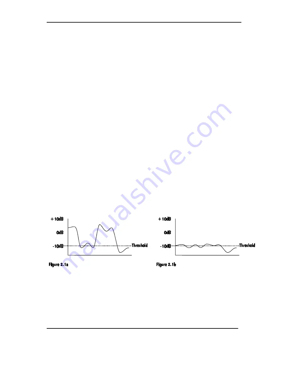
Consider an input signal which is applied to two units, one having its threshold
point set 10dB higher than the other 

(See figures 2.1 a/b)

. Since the compressor

only affects signals that exceed the threshold level, that in figure 2.1a will be more
affected than that in figure 2.1b.

Summary of Contents for DPR 402

Page 1: ...T SHOULD NOT BE NECESSARY TO REMOVE ANY PROTECTIVE EARTH OR SIGNAL CABLE SHIELD CONNECTIONS TO PREVENT GROUND LOOPS ANY SUCH DISCONNECTIONS ARE OUTSIDE THE RECOMMENDED PRACTISE OF BSS AUDIO AND WILL R...

Page 2: ...ons Rear Panel Facilities 10 9 1 Inputs 10 9 2 Outputs 11 9 3 Stereo Link 11 9 4 Barrier Strip 11 9 5 Peak Limiter Switch 11 10 Compression Controls 12 10 1 Threshold 12 10 2 Ratio 12 10 3 Attack Time...

Page 3: ...Dynamic Control 22 14 5 De ess HF with Full Dynamic Control 23 14 6 Peak Limiting 24 15 Applications using the Barrier Strip 24 15 1 Patching of External Equipment 24 15 2 Repatching of the Barrier St...

Page 4: ...l The safety margin is known as headroom and is generally in the range of 10 to 20dB Lowering the standard operating level to increase headroom helps distortion but moves the average program level nea...

Page 5: ...el However program signals in excess of this threshold will be progressively reduced by an amount ratio depending on the degree to which it initially exceeds the threshold Generally threshold levels f...

Page 6: ...ect that of the dynamic time settings for attack and release For compressors a slow attack and release time is generally used in order to keep the overall output signal within a specified dynamic rang...

Page 7: ...s sound These high frequency or sibilant sounds can reach levels considerably greater than the normal voice level and will result in signal break up or distortion It is possible to control these sound...

Page 8: ...urpose use The control and subtract side chain insertion points allow numerous applications for the patching of the units own or external filters to provide dynamic tonal modification The calibrated p...

Page 9: ...integral moulded 3 pin connector which is provided to satisfy required local standards The mains voltage selector switch provides a simple external adjustment to allow operation on all international...

Page 10: ...he same grounding circuit The unit must NOT be operated unless the power cables ground earth wire is properly terminated it is important for personal safety as well as for proper control over the syst...

Page 11: ...esponds to the largest signal present When in stereo mode the front panel LINK LED will illuminate and care should be taken to ensure that both channels have their controls set equally For other metho...

Page 12: ...he top 22dB 12 10 22dB of the signal can be compressed The THRESHOLD control is adjustable from 30dBv to over 20dBv It should be noted that when the THRESHOLD control is set fully clockwise to the pos...

Page 13: ...very much dependant on program type and the setting of a wrong speed will result in either of two conditions If set too fast the overall volume level will jump up and down exactly following the peaks...

Page 14: ...that in the bypass mode the input is still connected to all of the DPR 402 circuitry so that all of the required facilities can be selected and set up This in conjunction with the OUTPUT METER and INP...

Page 15: ...depends on the threshold ratio attack and release time settings If for example a particular signal transient exceeds the threshold point by 10dB and the ratio knob is set to 2 1 then we would expect t...

Page 16: ...hat the input and output levels are similar the GAIN control will only affect the output signal level Once satisfied of this condition operation of the BYPASS switch will ensure an unnoticeable drop i...

Page 17: ...l of the DPR 402 utilising DE ESS and FREQ controls or exclusively on the one channel by setting the MODE switch to DE ESS WIDE and utilising the compressor section controls In utilising the controls...

Page 18: ...ing the MON S C switch This replaces the normal signal at the output connector with the output of the de ess filter 12 4 Peak Limiting Referring back to section 3 De essing and Peak Limiting the probl...

Page 19: ...tions to the subtract side chain will be phase conscious whereas those to the control will not be Any externally connected equipment should operate at unity gain and be capable of handling signal leve...

Page 20: ...ompressed output signal can now be compared on the output meter by operating the METER INPUT switch Final adjustments of the controls can then be made to suit particular requirements including the RAT...

Page 21: ...4 3 De essing Wide with Simultaneous Compression Barrier strip linking B C and D G as factory set Initial settings Set all compressor controls as required refer to section 14 1 Compression For optimum...

Page 22: ...UCTION meter The FREQ control and THRESHOLD control can now be fine tuned to achieve the desired effect whilst listening to the program Gain compensation will not normally be required when de essing A...

Page 23: ...ted on the GAIN REDUCTION meter The FREQ control and THRESHOLD control can now be fine tuned to achieve the desired effect whilst listening to the program Gain compensation will not normally be requir...

Page 24: ...ternal Equipment Control Side Chain A very common requirement is to make the threshold of the compressor frequency conscious by inserting a graphic or parametric equaliser into the control side chain...

Page 25: ...and other combinations may be tried To obtain the full benefits of its versatility a simple understanding of how it works is required refer to section 13 Rear Barrier Strip MODE SUBTRACT S C LINK CON...

Page 26: ...ce the subtract side chain signal is added to the main signal The DE ESSER should not normally be used in this mode The PEAK LIMITER may be used for effect C G H J D B EXPANDER L F ONLY As above but o...

Page 27: ...oment in time otherwise the stereo image will move around the sound picture as the relative levels of the left and right hand signals vary Stereo linking couples together the compressor control signal...

Page 28: ...e only the controls on Channel 1 compressor will be required to control both channels as the control signal for channel 1s VCA is used to drive that on channel 2 This gives excellent stereo matching w...

Page 29: ...hen the repair has been completed If the unit was purchased in the European Union you may as an alternative return the unit to any other BSS distributor in the European Union You should include a stat...

Page 30: ...2 at 1kHz IMD 0 01 SMPTE Typically 0 003 10dB compression Threshold 0dB 1kHz 5sec rel Time see note 1 2nd Harmonic 0 15 3rd Harmonic 0 05 IMD SMPTE 0 25 Cross Talk Better than 85dB 20Hz to 20kHz any s...

Page 31: ...ith reduced frequency and shorter time constants which is inherent in this type of equipment Note 2 Attack times are those as measured to achieve 63 of final gain reduction with a step signal of 8dB a...

Page 32: ...l from 24dBm to 18dBm Display bright up at 21dBm clip DE ESS 2 LEDs to indicate normal and hard de essing PEAK LIMITING 2 LEDs to indicate normal and hard peak limiting Stereo Switch Couples channel 1...

Reviews: