935CA: Installation, Start-up, Operating and Service and Maintenance Instructions
Manufacturer reserves the right to change, at any time, specifications and designs without notice and without obligations.
6
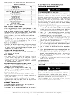
Table 2 – Loose Parts Bag
CODES AND STANDARDS
Follow all national and local codes and standards in addition to these
instructions. The installation must comply with regulations of the
serving gas supplier, local building, heating, plumbing, and other codes.
In absence of local codes, the installation must comply with the national
codes listed below and all authorities having jurisdiction.
In the United States, follow all codes and standards for the following:
Safety
• Current edition of US: National Fuel Gas Code (NFGC) NFPA
54/ANSI Z223.1 and the Installation Standards, Warm Air Heating
and Air Conditioning Systems ANSI/NFPA 90B
General Installation
• US: NFGC and the NFPA 90B. For copies, contact the National Fire
Protection Association Inc., Batterymarch Park, Quincy, MA 02269;
or for only the NFGC contact the American Gas Association, 400 N.
Capitol, N.W., Washington DC 20001
Combustion and Ventilation Air
• US: Current edition of Section 9.3 of the NFPA54/ANSI Z223.1 Air
for Combustion and Ventilation
Duct Systems
• US: Current edition of Air Conditioning Contractors Association
(ACCA) Manual D, Sheet Metal and Air Conditioning Contractors
National Association (SMACNA), or American Society of Heating,
Refrigeration, and Air Conditioning Engineers (ASHRAE)
Fundamentals Handbook Chapter 35
Acoustical Lining and Fibrous Glass Duct
• US: Current edition of SMACNA, NFPA 90B as tested by UL
Standard 181 for Class I Rigid Air Ducts
Gas Piping and Gas Pipe Pressure Testing
• US: Current edition of NFPA 54/ANSI Z223.1 NFGC; Chapters 5, 6,
7, and 8 and national plumbing codes.
In the state of Massachusetts:
• This product must be installed by a licensed plumber or gas fitter.
• When flexible connectors are used, the maximum length shall not
exceed 36 in. (914 mm).
• When lever type gas shutoffs are used they shall be T-handle type.
• The use of copper tubing for gas piping is not approved by the state of
Massachusetts.
Electrical Connections
• US: Current edition of National Electrical Code (NEC) NFPA 70
Condensate Drain Connection
• US: Current edition of National Standard Plumbing Code, Section 8.7.
ELECTROSTATIC DISCHARGE (ESD)
PRECAUTIONS PROCEDURE
1. Disconnect all power to the furnace. Multiple disconnects may be
required. DO NOT TOUCH THE CONTROL OR ANY WIRE
CONNECTED TO THE CONTROL PRIOR TO DISCHARGING
YOUR BODY’S ELECTROSTATIC CHARGE TO GROUND.
2. Firmly touch the clean, unpainted, metal surface of the furnace
chassis which is close to the control. Tools held in a person’s hand
during grounding will be satisfactorily discharged.
3. After touching the chassis, you may proceed to service the control
or connecting wires as long as you do nothing to recharge your
body with static electricity (for example; DO NOT move or shuffle
your feet, do not touch ungrounded objects, etc.).
4. If you touch ungrounded objects (and recharge your body with
static electricity), firmly touch a clean, unpainted metal surface of
the furnace again before touching control or wires.
5. Use this procedure for installed and uninstalled (ungrounded)
furnaces.
6. Before removing a new control from its container, discharge your
body’s electrostatic charge to ground to protect the control from
damage. If the control is to be installed in a furnace, follow items 1
through 4 before bringing the control or yourself in contact with the
furnace. Put all used and new controls into containers before
touching ungrounded objects.
7. An ESD service kit (available from commercial sources) may also
be used to prevent ESD damage.
ACCESSORIES
See Product Data Sheet for a list of accessories for this product.
LOCATION
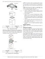
IMPORTANT:
IMPORTANT: Clearances for Condensate Trap
Before locating furnace, refer to condensate trap installation instructions
section for required clearances for trap installation.
DESCRIPTION
QTY
Air Intake Pipe Flange
1
Vent Pipe Flange
1
Pipe Flange Gaskets
2
Sharp Tip Screws (Vent and Inlet Flanges)
10
Vent Pipe Coupling
1
Vent Pipe Coupling Clamps
2
Gas Line Grommet
1
Junction Box Cover
1
Junction Box Base
1
Green Ground Screw
1
Blunt Tip Screws (Junction Box)
3
Thermostat Wire Grommet
1
Rubber Drain Elbow
1
Drain Tube Clamps
2
1/2-in. CPVC to 3/4-in. PVC Pipe Adapter
1
CAUTION
!
FURNACE RELIABILITY HAZARD
Failure to follow this caution may result in unit component damage.
Electrostatic discharge can affect electronic components. Take
precautions during furnace installation and servicing to protect the
furnace electronic control. Precautions will prevent electrostatic
discharges from personnel and hand tools which are held during the
procedure. These precautions will help to avoid exposing the control to
electrostatic discharge by putting the furnace, the control, and the
person at the same electrostatic potential.
CAUTION
!
PERSONAL RELIABILITY HAZARD
Failure to follow this caution may result in unit component damage.
Furnace may not be used for heating buildings under construction.


