


935CA: Installation, Start-up, Operating and Service and Maintenance Instructions
Manufacturer reserves the right to change, at any time, specifications and designs without notice and without obligations.
19
A200088
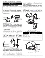
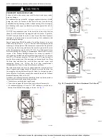
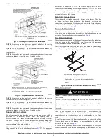
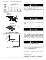
Fig. 32 – Working Platform for Attic Installation
NOTE:
Furnace shown is a direct vent application. Refer to the venting
section for allowable vent configurations.
NOTE:
N Coil only, add 8-in. separation between coil and furnace for
all other unshielded coils, see evaporator coil spacer or shield
requirements.)
NOTE:
Local codes may require a drain pan and condensate trap when a
condensing furnace is installed over a finished ceiling.
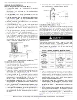
A200085
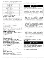
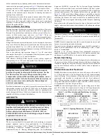
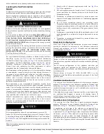
Fig. 33 – Suspended Furnace Installation
NOTE:
Furnace shown is a direct vent application. Refer to the venting
section for allowable vent configurations.
NOTE:
N Coil only, add 8-in. separation between coil and furnace for
all other unshielded coils, see evaporator coil spacer or shield
requirements.)
NOTE:
Local codes may require a drain pan and condensate trap when a
condensing furnace is installed over a finished ceiling.
Supply Air Connections
For a furnace not equipped with a cooling coil, the outlet duct shall be
provided with a removable access panel. This opening shall be
accessible when the furnace is installed and shall be of such a size that
the heat exchanger can be viewed for possible openings using light
assistance or a probe can be inserted for sampling the air stream. The
cover attachment shall prevent leaks.
Connect supply-air duct to flanges on furnace supply-air outlet. Bend
flange upward to 90° with wide duct pliers, see
Fig. 27
. The supply-air
duct must be connected to ONLY the furnace supply-outlet-air duct
flanges or air conditioning coil casing (when used). DO NOT cut main
furnace casing side to attach supply air duct, humidifier, or other
accessories. All supply-side accessories MUST be connected to duct
external to furnace main casing.
Return Air Connections
The return-air duct may be connected to bottom of the furnace. The side
of casing that faces downward may also be used for return air
connection. A combination of the bottom and downward facing side may
also be used. The upward facing side of the casing cannot be used as a
return air connection, see
Fig. 29
.
Bottom Return Air Inlet
These furnaces are shipped with bottom closure panel installed in bottom
return-air opening. Remove and discard this panel when bottom return
air is used. To remove bottom closure panel, see
Fig. 34
.
Side Return Air Inlet
These furnaces are shipped with bottom closure panel installed in bottom
return-air opening. This panel MUST be in place when side return air
inlet(s) are used without a bottom return air inlet.
Not all horizontal furnaces are approved for side return air connections,
see
Fig. 29
. Where required by code, seal bottom closure to furnace with
tape, mastic, or other durable sealing method.
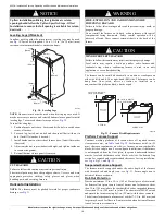
A170123
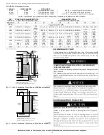
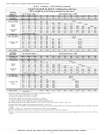
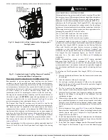
Fig. 34 – Removing Bottom Closure Panel (2 Screws)
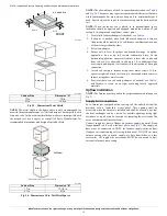
Filter Arrangement
There are no provisions for an internal filter in these furnaces. An
external filter rack is required and is purchased separately. A field
supplied accessory air cleaner may also be used in place of the filter
rack.
For upflow applications, the filter can be installed on either side of the
furnace, the bottom of the furnace or any combination of side and
bottom of the furnace, see
Fig. 28
.
For horizontal applications, the filter rack (or field supplied accessory air
cleaner) can be connected to the bottom opening on the furnace. For side
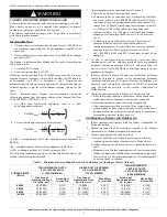
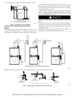
ADDITIONAL 1” CLEARANCE BELOW TRAP RECOMMENDED
FOR SERVICE
6-3/8” CLEARANCE
NEEDED FOR TRAP
NOTE
: FURNACE SHOWN IS A DIRECT VENT APPLICATION. REFER TO THE
VENTING SECTION FOR ALLOWABLE VENT CONFIGURATIONS.
NOTE
:
(N
COIL
ONLY,
ADD
8"
SEPARATION
BETWEEN
COIL
&
FURNACE
FOR
ALL
OTHER
UNSHIELDED
COILS)
SEE EVAPORATOR COIL SPACER OR
SHIELD REQUIREMENTS.
6-3/8” CLEARANCE
NEEDED FOR TRAP
ADDITIONAL 1”
CLEARANCE BELOW TRAP
RECOMMENDED
FOR SERVICE
WARNING
!
FIRE, CARBON MONOXIDE AND POISONING
HAZARD
Failure to follow this warning could result in fire, personal injury or
death.
Never operate a furnace without a filter or filtration device installed.
Never operate a furnace with filter or filtration device access doors
removed.
1.
Lay furnace on the back or side
2.
Remove the two (2) screws that secure the bottom
closure panel to the furnace casing and remove the
panel
SCREWS (2)
BOTTOM
CLOSURE
Representative drawing. Models may vary.