935CA: Installation, Start-up, Operating and Service and Maintenance Instructions
Manufacturer reserves the right to change, at any time, specifications and designs without notice and without obligations.
53
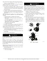
(1.)Remove thermostat from subbase or from wall.
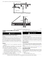
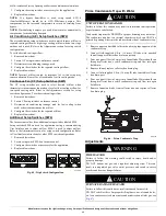
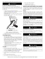
(2.)Connect an amp. meter (see
Fig. 69
) across the R and W/W1
subbase terminals or R and W/W1 wires at wall.
(3.)Record amp. draw across terminals when furnace is in heating
and after blower starts.
(4.)Set heat anticipator on thermostat per thermostat instructions
and install on subbase or wall.
A96316
Fig. 69 – Amp. Draw Check With Ammeter
a. Electronic thermostat: Set cycle rate for 4 cycles per hr.
2. Cooling On Delay is fixed at 2 seconds for either jumper selection.
Check Safety Controls
1. Check Main Limit Switch(es)
This control shuts off combustion control system and energizes
air-circulating blower motor, if furnace overheats. By using this
method to check limit control, it can be established that limit is
functioning properly and will operate if there is a restricted duct
system or motor failure. If limit control does not function during
this test, cause must be determined and corrected.
a. Run furnace for at least 5 minutes.
b. Gradually block off return air with a piece of cardboard or sheet
metal until the limit trips.
c. Unblock return air to permit normal circulation for 5 minutes.
d. Main limit circuit open causes 3 hour lock out.
e. Reset unit power to clear limit fault lockout.
Checklist
1. Put away tools and instruments. Clean up debris.
2. Verify that switches SW1-1 and SW1-6 are
OFF
and other setup
switches are set as desired. Verify that switches SW1-7 and SW1-8
for the blower
OFF DELAY
are set as desired per
Table 25
.
3. Verify that blower and control doors are properly installed.
4. Verify that there are no unsealed openings in the blower shelf or
casing.
5. Cycle test furnace with room thermostat.
6. Check operation of accessories per manufacturer’s instructions.
7. Review Owner’s Manual with owner.
8. Attach literature packet to furnace.
9. Attach entire literature packet to furnace.
SERVICE AND MAINTENANCE PROCEDURES
Untrained personnel can perform basic maintenance functions such as
cleaning and replacing air filters. All other operations must be performed
by trained service personnel. A qualified service person should inspect
the furnace once a year.
General
These instructions are written as if the furnace is installed in an upflow
application. An upflow furnace application is where the blower is
located below the combustion and controls section of the furnace, and
conditioned air is discharged upward. Since this furnace can be installed
in any of the 3 positions (see
Fig. 4
), you must revise your orientation to
component location accordingly.
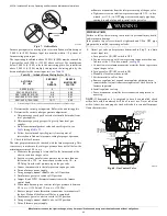
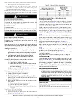
CAUTION
!
FURNACE OVERHEATING HAZARD
Failure to follow this caution may result in reduced furnace life.
Recheck temperature rise. It must be within limits specified on the
rating plate. Recommended operation is at the mid-point of rise range
or slightly above.
R Y W G
10 TURNS
THERMOSTAT SUBBASE
TERMINALS WITH
THERMOSTAT REMOVED
(ANITICIPATOR, CLOCK, ETC.,
MUST BE OUT OF CIRCUIT.)
HOOK-AROUND
AMMETER
EXAMPLE:
5.0 AMPS ON AMMETER
10 TURNS AROUND JAWS
=
0.5 AMPS FOR THERMOSTAT
ANTICIPATOR SETTING
FROM UNIT 24-V
CONTROL TERMINALS
WARNING
!
FIRE, INJURY OR DEATH HAZARD
Failure to follow this warning could result in personal injury, death
and/or property damage.
The ability to properly perform maintenance on this equipment requires
certain knowledge, mechanical skills, tools, and equipment. If you do
not possess these, do not attempt to perform any service and
maintenance on this equipment other than those procedures
recommended in the Owner’s Manual.
CAUTION
!
ENVIRONMENTAL HAZARD
Failure to follow this caution may result in environmental pollution.
Remove and recycle all components or materials (i.e. oil, refrigerant,
control board, etc.) before unit final disposal.
WARNING
!
ELECTRICAL SHOCK, FIRE OR EXPLOSION HAZARD
Failure to follow this warning could result in personal injury or death,
or property damage.
Before installing, modifying, or servicing system, main electrical
disconnect switch must be in the OFF position and install a lockout tag.
There may be more than one disconnect switch. Lock out and tag
switch with a suitable warning label. Verify proper operation after
servicing. Always reinstall access doors after completing service and
maintenance.
CAUTION
!
ELECTRICAL OPERATION HAZARD
Failure to follow this caution may result in improper furnace operation
or failure of furnace.
Label all wires prior to disconnection when servicing controls. Wiring
errors can cause improper and dangerous operation.

