


7
UNIT DAMAGE HAZARD
Failure to follow this caution may result in accelerated
corrosion of unit parts.
Harsh chemicals, household bleach or acid or basic
cleaners should not be used to clean outdoor or indoor
coils of any kind. These cleaners can be very difficult
to rinse out of the coil and can accelerate corrosion at
the fin/tube interface where dissimilar materials are in
contact. If there is dirt below the surface of the coil,
use the Totaline environmentally sound coil cleaner.
CAUTION
!
UNIT DAMAGE HAZARD
Failure to follow this caution may result in reduced
unit performance or unit shutdown.
High velocity water from a pressure washer, garden
hose, or compressed air should never be used to
clean a coil. The force of the water or air jet will
bend the fin edges and increase airside pressure drop.
CAUTION
!
Totaline Environmentally Sound Coil Cleaner
Application Instructions
1. Proper eye protection such as safety glasses is recom-
mended during mixing and application.
2. Remove all surface loaded fibers and dirt with a vacu-
um
cleaner as described above.
3. Thoroughly wet finned surfaces with clean water and
a low velocity garden hose, being careful not to bend
fins.
4. Mix Totaline environmentally sound coil cleaner in a
2--1/2 gallon garden sprayer according to the instruc-
tions included with the cleaner. The optimum solution
temperature is 100
_
F.
NOTE
: Do NOT USE water in excess of 130
_
F, as the
enzymatic activity will be destroyed.
5. Thoroughly apply Totaline environmentally sound
coil cleaner solution to all coil surfaces including
finned area, tube sheets and coil headers.
6. Hold garden sprayer nozzle close to finned areas and
apply cleaner with a vertical, up--and--down motion.
Avoid spraying in horizontal pattern to minimize po-
tential for fin damage.
7. Ensure cleaner thoroughly penetrates deep into finned
areas.
8. Interior and exterior finned areas must be thoroughly
cleaned.
9. Finned surfaces should remain wet with cleaning
solution for 10 minutes.
10. Ensure surfaces are not allowed to dry before rinsing.
Reapplying cleaner as needed to ensure 10--minute
saturation is achieved.
11. Thoroughly rinse all surfaces with low velocity clean
water using downward rinsing motion of water spray
nozzle. Protect fins from damage from the spray
nozzle.
Evaporator Coil
Cleaning the Evaporator Coil
1. Turn unit power off. Install lockout tag. Remove
evaporator coil access panel.
2. If economizer or two--position damper is installed, re-
move economizer by disconnecting Molex plug and
removing mounting screws.
3. Slide filters out of unit.
4. Clean coil using a commercial coil cleaner or dish-
washer detergent in a pressurized spray canister. Wash
both sides of coil and flush with clean water. For best
results, back--flush toward return--air section to re-
move foreign material. Flush condensate pan after
completion.
5. Reinstall economizer and filters.
6. Reconnect wiring.
7. Replace access panels.
Evaporator Coil Metering Devices
The metering devices are multiple fixed--bore devices
(Acutrol
t
) swedged into the horizontal outlet tubes from
the liquid header, located at the entrance to each
evaporator coil circuit path. These are non--adjustable.
Service requires replacing the entire liquid header
assembly.
To check for possible blockage of one or more of these
metering devices, disconnect the supply fan contactor
(IFC) coil, then start the compressor and observe the
frosting pattern on the face of the evaporator coil. A frost
pattern should develop uniformly across the face of the
coil starting at each horizontal header tube. Failure to
develop frost at an outlet tube can indicate a plugged or a
missing orifice.
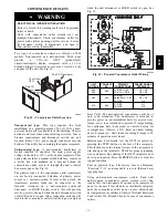
Refrigerant System Pressure Access Ports
There are two access ports in the system -- on the suction
tube near the compressor and on the discharge tube near
the compressor. These are brass fittings with black plastic
caps. The hose connection fittings are standard 1/4 SAE
Male Flare couplings.
The brass fittings are two--piece High Flow valves, with a
receptacle base brazed to the tubing and an integral
spring--closed check valve core screwed into the base.
(See Fig. 11.) This check valve is permanently assembled
into this core body and cannot be serviced separately;
replace the entire core body if necessary. Service tools are
available from RCD that allow the replacement of the
check valve core without having to recover the entire
system refrigerant charge. Apply compressor refrigerant
oil to the check valve core’s bottom o--ring. Install the
fitting body with 96 +/--10 in--lbs of torque; do not
overtighten.
580J
Summary of Contents for 580J*04--12
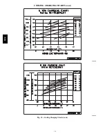
Page 9: ...9 COOLING CHARGING CHARTS C08203 C08204 Fig 12 Cooling Charging Charts 580J ...
Page 10: ...10 COOLING CHARGING CHARTS cont C08228 C08229 Fig 12 Cooling Charging Charts cont 580J ...
Page 11: ...11 COOLING CHARGING CHARTS cont C08437 C08438 Fig 12 Cooling Charging Charts cont 580J ...
Page 12: ...12 COOLING CHARGING CHARTS cont C08439 Fig 12 Cooling Charging Charts cont 580J ...
Page 46: ...46 C08308 Fig 52 580J Typical Unit Wiring Diagram Power 06A B C 208 230 3 60 580J ...
Page 47: ...47 C08317 Fig 53 580J Unit Wiring Diagram Control 06A B C 580J ...


