


34
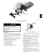
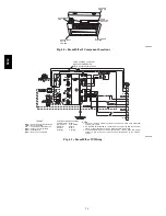
ECONOMI$ER2
PLUG
BAROMETRIC
RELIEF
DAMPER
OUTDOOR
AIR HOOD
HOOD
SHIPPING
BRACKET
GEAR DRIVEN
DAMPER
C06022
Fig. 40 -- EconoMi$er2 Component Locations
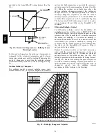
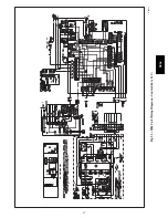
FOR OCCUPANCY CONTROL
REPLACE JUMPER WITH
FIELD-SUPPLIED TIME CLOCK
LEGEND
DCV—
Demand Controlled Ventilation
IAQ —
Indoor Air Quality
LA —
Low Ambient Lockout Device
OAT —
Outdoor-Air Temperature
POT —
Potentiometer
RAT —
Return-Air Temperature
Potentiometer Defaults Settings:
Power Exhaust Middle
Minimum Pos.
Fully Closed
DCV Max.
Middle
DCV Set
Middle
Enthalpy
C Setting
NOTES:
1. 620 ohm, 1 watt 5% resistor should be removed only when using differential
enthalpy or dry bulb.
2. If a separate field-supplied 24 v transformer is used for the IAQ sensor power
supply, it cannot have the secondary of the transformer grounded.
3. For field-installed remote minimum position POT, remove black wire jumper
between P and P1 and set control minimum position POT to the minimum
position.
8
7
C06028
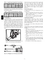
Fig. 41 -- EconoMi$er IV Wiring
580J
Summary of Contents for 580J*04--12
Page 9: ...9 COOLING CHARGING CHARTS C08203 C08204 Fig 12 Cooling Charging Charts 580J ...
Page 10: ...10 COOLING CHARGING CHARTS cont C08228 C08229 Fig 12 Cooling Charging Charts cont 580J ...
Page 11: ...11 COOLING CHARGING CHARTS cont C08437 C08438 Fig 12 Cooling Charging Charts cont 580J ...
Page 12: ...12 COOLING CHARGING CHARTS cont C08439 Fig 12 Cooling Charging Charts cont 580J ...
Page 46: ...46 C08308 Fig 52 580J Typical Unit Wiring Diagram Power 06A B C 208 230 3 60 580J ...
Page 47: ...47 C08317 Fig 53 580J Unit Wiring Diagram Control 06A B C 580J ...


