


36
C06053
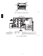
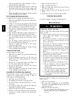
Fig. 43 -- EconoMi$er IV Functional View
EconoMi$er IV
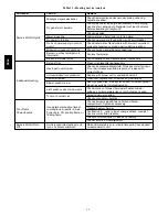
Table 15 provides a summary of EconoMi$er IV.
Troubleshooting instructions are enclosed.
A functional view of the EconoMi$er is shown in Fig. 43.
Typical settings, sensor ranges, and jumper positions are
also shown. An EconoMi$er IV simulator program is
available from Bryant to help with EconoMi$er IV
training and troubleshooting.
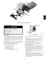
EconoMi$er IV Standard Sensors
Outdoor Air Temperature (OAT) Sensor
The outdoor air temperature sensor (HH57AC074) is a 10
to 20 mA device used to measure the outdoor-air
temperature. The outdoor-air temperature is used to
determine when the EconoMi$er IV can be used for free
cooling. The sensor is factory-installed on the
EconoMi$er IV in the outdoor airstream. (See Fig. 44.)
The operating range of temperature measurement is 40
_
to
100
_
F (4
_
to 38
_
C).
Supply Air Temperature (SAT) Sensor
The supply air temperature sensor is a 3 K thermistor
located at the inlet of the indoor fan. (See Fig. 44.) This
sensor is factory installed. The operating range of
temperature measurement is 0
°
to 158
_
F (--18
_
to 70
_
C).
See Table 16 for sensor temperature/resistance values.
Table 16 – Thermistor Resistance vs Temperature
Values for Space Temperature Sensor, Supply Air
Temperature Sensor, and Outdoor Air Temperature
Sensor
TEMP
(C)
TEMP
(F)
RESISTANCE
(Ohms)
---40
---40
335,651
---35
---31
242,195
---30
---22
176,683
---25
---13
130,243
---20
---4
96,974
---15
5
72,895
---10
14
55,298
---5
23
42,315
0
32
32,651
5
41
25,395
10
50
19,903
15
59
15,714
20
68
12,494
25
77
10,000
30
86
8,056
35
95
6,530
40
104
5,325
45
113
4,367
50
122
3,601
55
131
2,985
60
140
2,487
65
149
2,082
70
158
1,752
580J
Summary of Contents for 580J*04--12
Page 9: ...9 COOLING CHARGING CHARTS C08203 C08204 Fig 12 Cooling Charging Charts 580J ...
Page 10: ...10 COOLING CHARGING CHARTS cont C08228 C08229 Fig 12 Cooling Charging Charts cont 580J ...
Page 11: ...11 COOLING CHARGING CHARTS cont C08437 C08438 Fig 12 Cooling Charging Charts cont 580J ...
Page 12: ...12 COOLING CHARGING CHARTS cont C08439 Fig 12 Cooling Charging Charts cont 580J ...
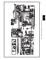
Page 46: ...46 C08308 Fig 52 580J Typical Unit Wiring Diagram Power 06A B C 208 230 3 60 580J ...
Page 47: ...47 C08317 Fig 53 580J Unit Wiring Diagram Control 06A B C 580J ...


