


18
tion of the flexible tubing to the sampling tube is the
same.
C08127
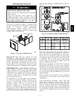
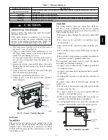
Fig. 22 -- Return Air Sensor Operating Position
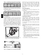
FIOP Smoke Detector Wiring and Response
All units: FIOP smoke detector is configured to
automatically shut down all unit operations when smoke
condition is detected. See Fig. 23, Smoke Detector
Wiring.
Highlight A: JMP 3 is factory--cut, transferring unit
control to smoke detector.
Highlight B: Smoke detector NC contact set will open on
smoke alarm condition, de--energizing the ORN
conductor.
Highlight C: 24--v power signal via ORN lead is removed
at Smoke Detector input on LCTB; all unit operations
cease immediately.
Using Remote Logic: Five conductors are provided for
field use (see Highlight D) for additional annunciation
functions.
Additional Application Data — Refer to Catalog No.
HKRNKA--1XA for discussions on additional control
features of these smoke detectors including multiple unit
coordination. See Fig. 23.
A
D
C
B
C08435
Fig. 23 -- Typical Smoke Detector System Wiring
580J
Summary of Contents for 580J*04--12
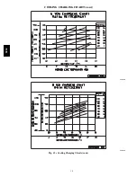
Page 9: ...9 COOLING CHARGING CHARTS C08203 C08204 Fig 12 Cooling Charging Charts 580J ...
Page 10: ...10 COOLING CHARGING CHARTS cont C08228 C08229 Fig 12 Cooling Charging Charts cont 580J ...
Page 11: ...11 COOLING CHARGING CHARTS cont C08437 C08438 Fig 12 Cooling Charging Charts cont 580J ...
Page 12: ...12 COOLING CHARGING CHARTS cont C08439 Fig 12 Cooling Charging Charts cont 580J ...
Page 46: ...46 C08308 Fig 52 580J Typical Unit Wiring Diagram Power 06A B C 208 230 3 60 580J ...
Page 47: ...47 C08317 Fig 53 580J Unit Wiring Diagram Control 06A B C 580J ...


