


21
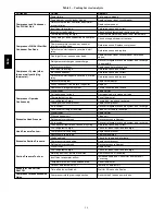
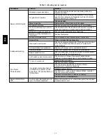
Table 3 – Detector Indicators
CONTROL OR INDICATOR
DESCRIPTION
Magnetic test/reset switch
Resets the sensor when it is in the alarm or trouble state. Activates or tests the sensor when it is in the
normal state.
Alarm LED
Indicates the sensor is in the alarm state.
Trouble LED
Indicates the sensor is in the trouble state.
Dirty LED
Indicates the amount of environmental compensation used by the sensor (flashing continuously = 100%)
Power LED
Indicates the sensor is energized.
OPERATIONAL TEST HAZARD
Failure to follow this caution may result in personnel
and authority concern.
If the smoke detector is connected to a fire alarm
system, first notify the proper authorities that the
detector is undergoing maintenance then disable the
relevant circuit to avoid generating a false alarm.
CAUTION
!
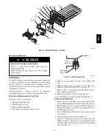
1. Disconnect power from the duct detector then remove
the sensor’s cover. (See Fig. 25.)
2. Using a vacuum cleaner, clean compressed air, or a
soft bristle brush, remove loose dirt and debris from
inside the sensor housing and cover.
Use isopropyl alcohol and a lint--free cloth to remove
dirt and other contaminants from the gasket on the
sensor’s cover.
3. Squeeze the retainer clips on both sides of the optic
housing then lift the housing away from the printed
circuit board.
4. Gently remove dirt and debris from around the optic
plate and inside the optic housing.
5. Replace the optic housing and sensor cover.
6. Connect power to the duct detector then perform a
sensor alarm test.
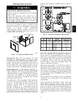
Airflow
HVAC duct
Sampling
tube
Retainer
clip
Optic
plate
Optic
housing
Sensor
housing
C07305
Fig. 25 -- Sensor Cleaning Diagram
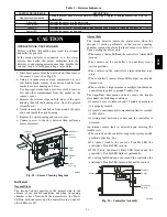
Indicators
Normal State
The smoke detector operates in the normal state in the
absence of any trouble conditions and when its sensing
chamber is free of smoke. In the normal state, the Power
LED on both the sensor and the controller are on and all
other LEDs are off.
Alarm State
The smoke detector enters the alarm state when the
amount of smoke particulate in the sensor’s sensing
chamber exceeds the alarm threshold value. (See Table 3.)
Upon entering the alarm state:
S
The sensor’s Alarm LED and the controller’s Alarm LED
turn on.
S
The contacts on the controller’s two auxiliary relays
switch positions.
S
The contacts on the controller’s alarm initiation relay
close.
S
The controller’s remote alarm LED output is activated
(turned on).
S
The controller’s high impedance multiple fan shutdown
control line is pulled to ground Trouble state.
The SuperDuct duct smoke detector enters the trouble
state under the following conditions:
S
A sensor’s cover is removed and 20 minutes pass before
it is properly secured.
S
A sensor’s environmental compensation limit is reached
(100% dirty).
S
A wiring fault between a sensor and the controller is
detected.
An internal sensor fault is detected upon entering the
trouble state:
S
The contacts on the controller’s supervisory relay switch
positions. (See Fig. 26.)
S
If a sensor trouble, the sensor’s Trouble LED the
controller’s Trouble LED turn on.
S
If 100% dirty, the sensor’s Dirty LED turns on and the
controller’s Trouble LED flashes continuously.
S
If a wiring fault between a sensor and the controller, the
controller’s Trouble LED turns on but not the sensor’s.
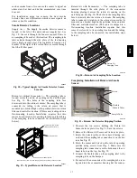
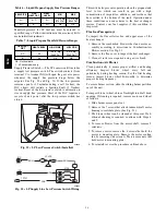
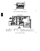
Alarm
Power
Test/reset
switch
Trouble
C07298
Fig. 26 -- Controller Assembly
580J
Summary of Contents for 580J*04--12
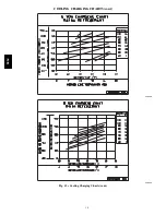
Page 9: ...9 COOLING CHARGING CHARTS C08203 C08204 Fig 12 Cooling Charging Charts 580J ...
Page 10: ...10 COOLING CHARGING CHARTS cont C08228 C08229 Fig 12 Cooling Charging Charts cont 580J ...
Page 11: ...11 COOLING CHARGING CHARTS cont C08437 C08438 Fig 12 Cooling Charging Charts cont 580J ...
Page 12: ...12 COOLING CHARGING CHARTS cont C08439 Fig 12 Cooling Charging Charts cont 580J ...
Page 46: ...46 C08308 Fig 52 580J Typical Unit Wiring Diagram Power 06A B C 208 230 3 60 580J ...
Page 47: ...47 C08317 Fig 53 580J Unit Wiring Diagram Control 06A B C 580J ...


