


29
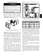
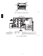
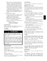
Red LED-Status
C08452
Fig. 38 -- Integrated Gas Control (IGC) Board
Table 9 – IGC Connections
TERMINAL LABEL
POINT DESCRIPTION
SENSOR LOCATION
TYPE OF I/O
CONNECTION
PIN NUMBER
INPUTS
RT, C
Input power from TRAN 1
control box
24 VAC
—
SS
Speed sensor
gas section
analog input
J1, 1-3
FS, T1
Flame sensor
gas section
switch input
—
W
Heat stage 1
LCTB
24 VAC
J2, 2
RS
Rollout switch
gas section
switch input
J2, 5-6
LS
Limit switch
fan section
switch input
J2, 7-8
CS
Centrifugal switch (not used)
—
switch input
J2, 9-10
OUTPUTS
L1, CM
Induced draft combustion motor
gas section
line VAC
IFO
Indoor fan
control box
relay
J2, 1
GV
Gas valve (heat stage 1)
gas section
relay
J2, 11-12
580J
Summary of Contents for 580J*04--12
Page 9: ...9 COOLING CHARGING CHARTS C08203 C08204 Fig 12 Cooling Charging Charts 580J ...
Page 10: ...10 COOLING CHARGING CHARTS cont C08228 C08229 Fig 12 Cooling Charging Charts cont 580J ...
Page 11: ...11 COOLING CHARGING CHARTS cont C08437 C08438 Fig 12 Cooling Charging Charts cont 580J ...
Page 12: ...12 COOLING CHARGING CHARTS cont C08439 Fig 12 Cooling Charging Charts cont 580J ...
Page 46: ...46 C08308 Fig 52 580J Typical Unit Wiring Diagram Power 06A B C 208 230 3 60 580J ...
Page 47: ...47 C08317 Fig 53 580J Unit Wiring Diagram Control 06A B C 580J ...


