


40
precautions to protect roofing. Procedures which risk oil
leakage include but are not limited to compressor
replacement,
repairing
refrigerants
leaks,
replacing
refrigerant components such as filter drier, pressure switch,
metering device, coil, accumulator, or reversing valve.
Synthetic Roof Precautionary Procedure:
1. Cover extended roof working area with an imper-
meable polyethylene (plastic) drop cloth or tarp.
Cover an approximate 10 x 10 ft (3.3 x 3.3 m) area.
2. Cover area in front of the unit service panel with a
terry cloth shop towel to absorb lubricant spills and
prevent run-offs, and protect drop cloth from tears
caused by tools or components.
3. Place terry cloth shop towel inside unit immediately un-
der component(s) to be serviced and prevent lubricant
run-offs through the louvered openings in the base pan.
4. Perform required service.
5. Remove and dispose of any oil contaminated material
per local codes.
Liquid Line Filter Drier —
The factory-provided filter drier is specifically designed to
operate with Puron
. Replace the filter drier with
factory-authorized components only with a filter drier
with desiccant made from 100% molecular sieve grade
XH-11. Filter drier must be replaced whenever the
refrigerant system is opened.
When removing a filter drier, use a tubing cutter to cut the
drier from the system.
Do not unsweat a filter drier
from
the system. Heat from unsweating will release moisture
and contaminants from drier into system.
Field Refrigerant Access Ports —
Field service access to refrigerant pressures is through the
access ports located at the service valves (see Figs 37 and
39). These ports are
-in SAE Flare couplings with
Schrader check valves and service caps. Use these ports to
admit nitrogen to the field tubing during brazing, to
evacuate the tubing and evaporator coil, to admit initial
refrigerant charge into the low-side of the system and
when checking and adjusting the system refrigerant
charge. When service activities are completed, ensure the
service caps are in place and secure; check for leaks. If
the Schrader check valve must be removed and
re-installed, tighten to 2-3 in-lbs (23-34 N-cm).
Factory High-Flow Access Ports —
There are two additional access ports in the system - on
the suction tube between the compressor and the suction
service valve and on the liquid tube near the liquid service
valve (see Figs 38 and 40). These are brass fittings with
black plastic caps. The hose connection fittings are
standard
-in SAE Male Flare couplings.
The brass fittings are two-piece High Flow valves, with a
receptacle base brazed to the tubing and an integral
spring-closed check valve core screwed into the base. (See
Fig. 34) This check valve is permanently assembled into
this core body and cannot be serviced separately; replace
the entire core body if necessary. Service tools are
available from RCD that allow the replacement of the
check valve core without having to recover the entire
system refrigerant charge. Apply compressor refrigerant
oil to the check valve core’s bottom o-ring. Install the
fitting body with 96
-10 in-lbs (1085
23 N-cm) of
torque; do not overtighten.
Hot Gas Bypass Valve Adjustments —
Refer to Fig. 32 for a unit piping schematic with factory
option Hot Gas Bypass control.
The suction pressure regulating valve is located between
the
unit’s
compressor
discharge
line
and
the
desuperheating tank. A suction pressure tube is connected
between the regulating valves and the unit suction line.
This valve is factory set to begin to open as suction
pressure drops below 109 psig (752 kPa). This valve can
be adjusted by removing the cover bolt on the valve to
expose the Allen key socket. One turn of this stem
provides a 5 psig (34 kPa) change in valve opening
setting. CW turn reduces the opening setting. CCW turn
increases the opening setting. MAXIMUM CCW
adjustment is one turn.
The factory setting is designed to provide a longer run
time during first stage cooling operation by beginning to
open at approximately 36
_
F (2
_
C) evaporator saturated
suction temperature as space load approaches satisfaction.
This extended run time will provide additional
dehumidification effect.
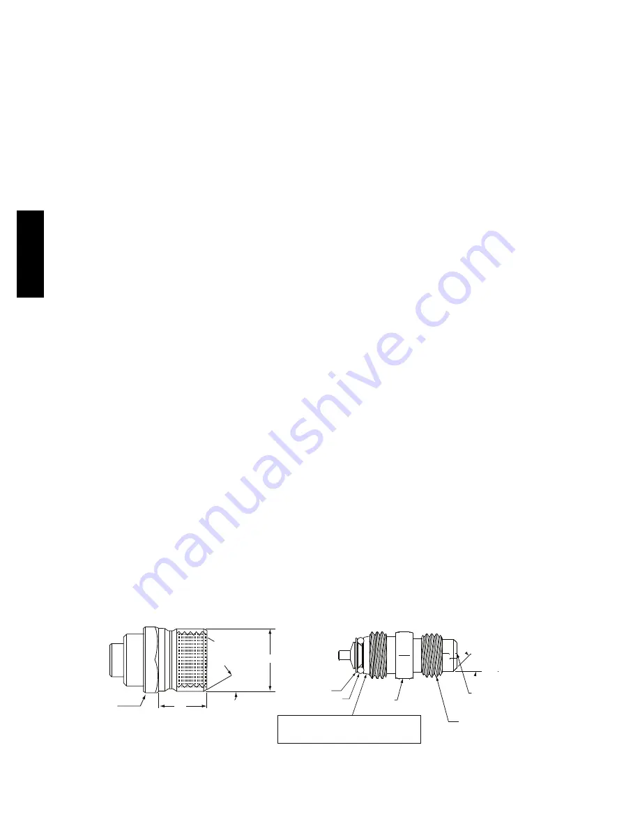
1/2-20 UNF RH
30°
0.596
.47
5/8” HEX
SEAT
CORE
WASHER
DEPRESSOR PER ARI 720
+.01/-.035
FROM FACE OF BODY
7/16-20 UNF RH
O-RING
45°
1/2" HEX
This surface provides a metal to metal seal when
torqued into the seat. Appropriate handling is
required to not scratch or dent the surface.
(Part No. EC39EZ067)
C08453
Fig. 34 -- CoreMax Access Port Assembly
569J
Summary of Contents for 569J Series
Page 34: ...34 C10925 Fig 29 Typical Single Circuit Single Stage 569J A B Wiring Diagram 569J ...
Page 35: ...35 C150339 Fig 30 Typical Single Circuit Two Stage 569J 07G H Wiring Diagram 569J ...
Page 36: ...36 C12547 Fig 31 Typical Dual Circuit Two Stage 569J D E F Wiring Diagram 569J ...
Page 53: ...53 D K J H G F E C B A C10800 Fig 44 Wind Baffles 569J ...


