Technical data
and startup
40
8.3
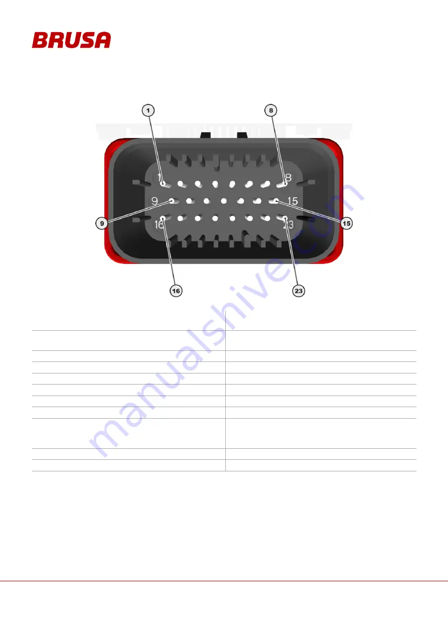
Pin assignment of control connector (device side)
1.
GND*
Ground (Minus wiring system,
terminal 31, input range 6
– 32V)
2.
AUX*
+12 V (Plus wiring system,
terminal 30, input range 6
– 32V)
3.
EN*
Enable (Power ON, terminal 15, input
range 6
– 32V)
4.
DO0
Reserve
5.
DO1
Reserve
6.
DO2
Reserve
7.
DO3
Reserve
8.
PG1
Ground reserve
9.
CNL*
CAN low
10.
CNH*
CAN high
11.
TXD**
RS232 Transmit (9 pole D-Sub pin 2)
12.
RXD**
RS232 Receive (9 pole D-Sub pin 3)
13.
PRO**
Enable firmware download
14.
PG2
Ground reserve
15.
PG3**
RS232 ground (9 pole D-Sub: pin 5)
16.
DI0
Reserve
17.
Ext. AW1*
External shut down path 1
(Plus wiring system, terminal 30,
input range 6
– 32V)
18.
Ext. AW2*
External shut down path 2
(Plus wiring system, terminal 30
Input range 6
– 32V)
19.
IL1*
Interlock signal loop
20.
IL2*
Interlock signal loop
21.
AI1
Reserve
22.
AI2
Reserve
23.
AI3
Reserve
*
= The connections must be wired for normal operation!
**
= Programming of the inverter is necessary!


