VPSB-DC and VPSB-DC-E
H172203_1_001
167 / 234
15 VPSB-DC and VPSB-DC-E
15.1
Introduction
The VPSB-DC (Variable Power Supply Board DC variant) is the successor of the Variable
Power Supply Board VPSB. In contrast to the VPSB, the new VPSB-DC uses only backplane
power and has no mains supply connector anymore. Also the control communication directly
goes through the backplane and is not looped through the Sensor and Pneumatic Board SPB
anymore.
The VPSB-DC is available in an extended version VPSB-DC-E, which includes a booster
functionality for WB Systems that can supply more output power to one of the two heater
power outputs.
The VPSB-DC integrates two mostly independent variable power sources in one 6TE 19“
unit, the VPSB-DC-E comes in a 12TE 19“ unit.
Low level hardware functions (e.g. safety circuits and A/D converter control) are implemented
directly on the VPBS-DC(-E), whereas higher level functions such as output power control
and read-out of the power monitoring are done by software running on the ELCB.
A two-stage watchdog system and a smart probe heater impedance meter circuit ensure safe
operation in case of serious malfunction.
The VPSB-DC(-E) has interfaces for connecting digital accessory sensors (temperature,
digital level sensors).
15.2
Configurations
There are two board variant available.
One VPSB-DC has two power outputs that allow to set-up two controlled temperature
channels.
One VPSB-DC-E has two power outputs that allow to set-up two controlled temperature
channels. The first channel can deliver more output power (booster functionality), if it is used
with a recent VT adapter. The overlying software will check that the VT adapter supports
booster operation, which is given if the device revision is at least 1. The figure below shows
how the VT adapter device revision can be checked on the AV4 BSMS service web variable
temperature control BFB overview.
Summary of Contents for NMR AV4 BSMS System
Page 1: ...BSMS System for AVANCE NEO User Manual Version 001 Innovation with Integrity NMR...
Page 10: ...Contents x H172203_1_001...
Page 22: ...Safety 22 234 H172203_1_001...
Page 26: ...Transport Packaging and Storage 26 234 H172203_1_001...
Page 42: ...Chassis Mainframe 42 234 H172203_1_001...
Page 46: ...Fan Tray 46 234 H172203_1_001...
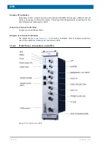
Page 55: ...ELCB H172203_1_001 55 234 Figure 8 1 ELCB Front Panel with LED s and Connectors...
Page 69: ...ELCB H172203_1_001 69 234 Figure 8 13 Lock RF Boards Diagnostics...
Page 70: ...ELCB 70 234 H172203_1_001...
Page 120: ...L TRX L 19F 120 234 H172203_1_001...
Page 148: ...BSVT Concept 148 234 H172203_1_001...
Page 166: ...SPB 166 234 H172203_1_001...
Page 172: ...VPSB DC and VPSB DC E 172 234 H172203_1_001 Figure 15 3 Block Diagram of the VPSB DC E...
Page 180: ...VPSB DC and VPSB DC E 180 234 H172203_1_001...
Page 187: ...VTA H172203_1_001 187 234 Figure 16 1 VTA Cable Connectors...
Page 193: ...VTA H172203_1_001 193 234 16 7 Ordering Information See Basic BSVT Configuration 124...
Page 194: ...VTA 194 234 H172203_1_001...
Page 200: ...Nitrogen Level Sensor 200 234 H172203_1_001...
Page 204: ...Radiation Shield Temperature Monitoring MAG RS 204 234 H172203_1_001...
Page 208: ...Installation and Initial Commissioning 208 234 H172203_1_001...
Page 210: ...Operation 210 234 H172203_1_001...
Page 216: ...Replacement of Parts 216 234 H172203_1_001...
Page 222: ...Contact 222 234 H172203_1_001...
Page 226: ...List of Figures 226 234 H172203_1_001...
Page 229: ...Glossary H172203_1_001 229 234 Glossary...
Page 230: ...Glossary 230 234 H172203_1_001...
Page 232: ...Index 232 234 H172203_1_001...
Page 233: ...H172203_1_001 233 234...
Page 234: ...Bruker Corporation info bruker com www bruker com Order No H172203...


