BSVT Concept
H172203_1_001
147 / 234
• When the target strength (= cooling power) of the cooling unit is set, nothing happens, and
the actual strength remains unchanged - why could this happen?
BSVT operation is required for activation of a connected cooling unit. As soon as the
BSVT is
On
, the actual cooling strength changes to the required value defined by the
target strength parameter. In addition, the rotary knob of the new BSCU cooling units must
be set to
Remote
position. Otherwise, the settings of the TopSpin software are ignored
and the locally set strength (by rotary knob position) is considered for operation.
Note: The BCU-X requires a minimum VT gas pressure and gas flow before it becomes
active. If there is no gas flow (or no gas supply) then a connected BCU-X cannot be
detected by the VT adapter.
• Which channel is the probe channel?
Probe channel identification is set to
Auto
by default (this setting can be defined on the
BSMS service Web under the menu
VT Configuration
).
Normally, there is a single heater device in the BSVT configuration, and the mapping is
therefore evident. Configurations for flow NMR applications can be handled automatically
as well - additional heaters are connected via specific VT adapters, and the remaining
active channel can therefore be considered as the probe channel. In applications with
several VT adapters of the same type (e. g. specific MAS configurations with separate
heaters for VT, bearing and rotation) it may be necessary to give an explicit definition of
the probe channel.
• How is the VT power represented in the new BSVT?
Inside the BSVT the VT power is represented in Watt (absolute power). However, the user
can select alternatively a relative representation for the GUI (percent). In that case the
reference power is the highest possible power that can be achieved with the connected
probe and the maximum voltage (48 Volt) of the VT power supply. Example:
– Cryo Probe heater with 48 Ohms: Imax = 1 A, Pmax = 48 Watt (= 100%)
• Has the maximum VT power setting an influence on the Self Tune?
The Self Tune is no longer affected by the maximum VT power (if it is high enough), since
the required power for Self Tune is evaluated in the beginning of the tuning automatically.
If the power limit is set too low, then the Self Tune aborts with a corresponding error
message (similar case if the chilling is not sufficient to reach the target temperature). The
temperature control process is not stopped in case of too restrictive power limitation (or
insufficient chilling), it is simply indicated in the regulator status that the heater power
limitation is too strict or that the chilling is not sufficient.
• Do I still need the cable Z13874 with VT power attenuator (with heat spreader) for
CryoProbes?
For operation of the former Variable Temperature control systems (e. g. BVT3000,
BVT3200) with CryoProbes, it was necessary to insert a power attenuator between the
BVT and the heater of the probe. The user could select between
Low
= 10%,
High
= 50%
and
ET
= 100% resulting VT power at the probe. With the new BSVT, this attenuator is no
longer used, since the VT power is provided by the BSVT in high resolution down to
smallest values and therefore also appropriate for direct operation with CryoProbes.
Problems with overheated attenuators or full power values varying with the selected power
range at the attenuator are eliminated with the BSVT.
Summary of Contents for NMR AV4 BSMS System
Page 1: ...BSMS System for AVANCE NEO User Manual Version 001 Innovation with Integrity NMR...
Page 10: ...Contents x H172203_1_001...
Page 22: ...Safety 22 234 H172203_1_001...
Page 26: ...Transport Packaging and Storage 26 234 H172203_1_001...
Page 42: ...Chassis Mainframe 42 234 H172203_1_001...
Page 46: ...Fan Tray 46 234 H172203_1_001...
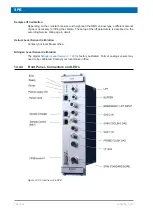
Page 55: ...ELCB H172203_1_001 55 234 Figure 8 1 ELCB Front Panel with LED s and Connectors...
Page 69: ...ELCB H172203_1_001 69 234 Figure 8 13 Lock RF Boards Diagnostics...
Page 70: ...ELCB 70 234 H172203_1_001...
Page 120: ...L TRX L 19F 120 234 H172203_1_001...
Page 148: ...BSVT Concept 148 234 H172203_1_001...
Page 166: ...SPB 166 234 H172203_1_001...
Page 172: ...VPSB DC and VPSB DC E 172 234 H172203_1_001 Figure 15 3 Block Diagram of the VPSB DC E...
Page 180: ...VPSB DC and VPSB DC E 180 234 H172203_1_001...
Page 187: ...VTA H172203_1_001 187 234 Figure 16 1 VTA Cable Connectors...
Page 193: ...VTA H172203_1_001 193 234 16 7 Ordering Information See Basic BSVT Configuration 124...
Page 194: ...VTA 194 234 H172203_1_001...
Page 200: ...Nitrogen Level Sensor 200 234 H172203_1_001...
Page 204: ...Radiation Shield Temperature Monitoring MAG RS 204 234 H172203_1_001...
Page 208: ...Installation and Initial Commissioning 208 234 H172203_1_001...
Page 210: ...Operation 210 234 H172203_1_001...
Page 216: ...Replacement of Parts 216 234 H172203_1_001...
Page 222: ...Contact 222 234 H172203_1_001...
Page 226: ...List of Figures 226 234 H172203_1_001...
Page 229: ...Glossary H172203_1_001 229 234 Glossary...
Page 230: ...Glossary 230 234 H172203_1_001...
Page 232: ...Index 232 234 H172203_1_001...
Page 233: ...H172203_1_001 233 234...
Page 234: ...Bruker Corporation info bruker com www bruker com Order No H172203...


