


147
POWERHEAD
CYLINDER HEAD
7
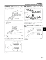
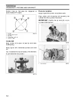
Lightly seat all cylinder head screws. Then
tighten, in stages, following the pattern shown.
•
Tighten to 20 ft. lbs. (28 N·m)
•
Loosen all screws completely
•
Tighten to 20 ft. lbs. (28 N·m)
•
Tighten to 40 ft. lbs. (55 N·m)
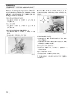
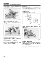
Place dowel pins and bottom crankcase gasket
into position.
IMPORTANT:
Before installing bottom crank-
case, make sure idle gear is in place and all timing
marks are aligned. Refer to
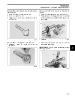
Place bottom crankcase into position.
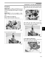
Install 8 mm and 10 mm screws from Crankshaft
Remover/Installer Kit, P/N 5037487, in positions
shown.
Tighten each screw gradually and evenly until
they bottom.
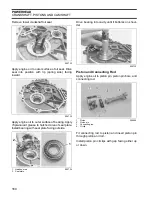
IMPORTANT:
Crankcase and cylinder block
surfaces should always be held parallel. Tap four
corners of crankcase with a rubber hammer while
gradually tightening screws.
When special tool screws have bottomed, replace
them with crankcase screws. Tighten screws as
follows:
•
8 mm: 16.5 ft. lbs. (23 N·m)
•
10 mm: 36 ft. lbs. (50 N·m)
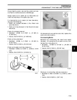
Torque Pattern – Cylinder Head
005693
1.
Dowel pins
005694
1
1
005695
005696


