


RH-981A
CONTENTS
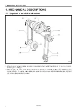
1. MECHANICAL DESCRIPTIONS
................... 1
1-1. Upper and lower shaft mechanisms .................. 1
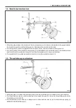
1-2. Needle bar mechanism ...................................... 2
1-3. Thread take-up mechanism ............................... 2
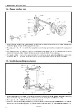
1-4. Zigzag mechanism ............................................. 3
1-5. Needle bar rocking mechanism ......................... 3
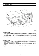
1-6. Feed mechanism ................................................ 4
1-7. Work clamp mechanism..................................... 5
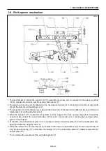
1-8. Cloth opener mechanism ................................... 6
1-9. Cutter mechanism............................................... 7
1-10. Looper mechanism ............................................. 7
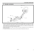
1-11. Spreader mechanism ......................................... 8
1-12. Double chain stitch looper mechanism.............. 9
2. DISASSEMBLY
................................................... 10
2-1. Covers and work clamp mechanism ...............10
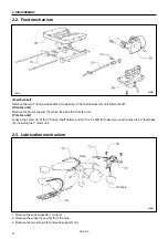
2-2. Feed mechanism ..............................................11
2-3. Lubrication mechanism ....................................11
2-4. Looper and spreader mechanisms..................12
2-5. Needle bar rotating mechanism .......................13
2-6. Looper base mechanism..................................14
2-7. Needle bar, thread take-up, and zigzag
mechanisms......................................................15
2-8. Knife pipe assembly..........................................17
2-9. Lower shaft mechanism ...................................17
2-10. Synchronizer mechanism.................................18
2-11. Upper shaft mechanism ...................................18
2-12. Cutter mechanism.............................................19
2-13. Zigzag fork mechanism ....................................19
3. ASSEMBLY
........................................................... 20
3-1. Zigzag fork mechanism ....................................20
3-2. Cutter mechanism.............................................21
3-3. Upper shaft mechanism ...................................22
3-4. Lower shaft mechanism ...................................23
3-4-1. Adjusting the timing belt..............................23
3-5. Upper thread trimmer mechanism ...................24
3-5-1. Adjusting the thread trimmer lever
hammer stroke ....................................................24
3-6. Knife pipe and the knife bracket.......................25
3-7. Driving gear shaft mechanism .........................26
3-8. Needle bar, thread take-up, and zigzag
mechanisms ......................................................27
3-8-1. Eliminating end play of the thread take-up
on the arm ...................................................27
3-8-2. Applying grease to the ends of the thread
take-up spring..............................................27
3-8-3.Eliminating end play of the needle bar
driving lever...................................................27
3-8-4.Eliminating end play of the driving rod ........28
3-8-5.The strength to tighten the set screw
of ball bearing 25/20.....................................28
3-8-6.Eliminating end play of the zigzag rock shaft ..... 28
3-8-7.Eliminating end play of the zigzag lever......29
3-8-8.Attaching the needle bar yoke and
the needle bar level feed link .......................29
3-8-9.Attaching the needle bar bush U and the
needle bar.....................................................30
3-8-10. Eliminating end play of
the needle bar block..................................31
3-8-11. Adjusting the needle bar
in the radial direction ...................................... 31
3-8-12. Attaching the needle bar block assembly....32
3-8-13. Adjusting the height of the needle bar .....32
3-9. Looper base.......................................................33
3-10. Needle bar rocking mechanism........................34
3-10-1. Driving looper shaft ...................................34
3-10-2. Needle bar rocking mechanism ...............35
3-11. Looper and spreader machanisms ..................37
3-12. Lubrication mechanism.....................................40
3-12-1. Machine head ...........................................40
3-12-2. Driving gear shaft.......................................41
3-13. Feed mechanism ..............................................42
3-13-1. X direction ...............................................42
3-13-2. Y direction ...............................................43
3-13-3. Attaching the X-feed guide shaft ...........45
3-14. Synchronizer......................................................46
3-15. Covers and work clamp mechanism................47
3-16. Safety switch......................................................47
4. ADJUSTMENT
.....................................................48
4-1. Adjusting the work clamp lift height ..................48
4-2. Adjusting the position of the work clamp plate .... 49
4-3. Adjusting the cloth opening amount.................50
4-4. Adjusting the position of the work clamp..........51
4-5. Adjusting the X-axis home position ..................52
4-6. Adjusting the Y-axis home position ..................52
4-7. Adjusting 0 position (reference line)
of the needle......................................................53
4-8. Adjusting the home position of the
looper base........................................................53
4-9. Fine adjustment of knife position......................54
4-10. Adjusting the sideways movement
of the cutter lever...............................................55
4-11. Adjusting the height of the throat plate.............55


