


7. SOFTWARE
RH-981A
125
Code
Countermeasure
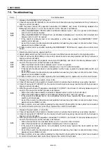
E-77
Refer to E70. (In input mode, check if the machine detects synchronizer signal.)
E-80
1. If X-axis pulse motor works, refer to E50. If not, proceed with the following steps to examine the
driving system of the X-axis pulse motor. (This is because the place to be checked is different if the
failure is with the sensor or driving system.)
2. With the power turned off, check if there is a loose screw in a belt or gear around the X-axis pulse
motor and that the feed bracket can move to the left and right.
3. Of the connectors relayed to the head harness, check if the connector for the X-axis pulse motor is
securely inserted and if any harness is broken or short-circuited.
4. Check if connector P7 (XPM) on the control circuit board is securely inserted and if any harness is
broken or short-circuited.
5. While E80 is displayed, measure the voltage across pins 5 and 7 of connector P12 (POWER)
without removing P12, from the harness, as follows:
• Considering pin 7 as 0V (standard), measure the voltage of pin 5. It is normal if the voltage is +
55V. (Be careful not to touch any other place when measuring voltage.)
* If the voltage is + 55V, the cause of the error is the X-axis pulse motor or its harness is broken.
* If the voltage is not + 55V, turn off the power, remove connector P12 (POWER), and then turn on
the power again, measure the voltage across pins 5 and 7 in the harness with connector P1
(POWER) inserted in the power supply circuit board in the same manner as above.
• If the voltage is not + 55V, replace the power supply circuit board.
* If the voltage is + 55V, the control circuit board or PMD circuit board for
θ
-axis may be damaged
or X-, Y-, or
θ
-axis pulse motor or its harness may be short-circuited.
E-81
1. If the Y-axis pulse motor works refer to E51. If not, proceed the following steps to examine the
driving system of Y-axis pulse motor. (This is because the place to be checked is different if the
failure is with the sensor or driving system.)
2. With the power turned off, check if there is a loose screw in a belt or gear around Y-axis pulse motor
and if the feed bracket can move back and forth.
3. Of the connectors relayed to the head harness, check if the connector for the Y-axis pulse motor is
securely inserted and if any harness is broken or short-circuited.
4. Check if connector P6 (YPM) on the control circuit board is securely inserted and if any harness is
broken or short-circuited.
5. While E81 is displayed, measure the voltage across pins 5 and 7 of connector P12 (POWER) on the
control circuit board without removing P12, from the harness, as follows:
• Considering pin 7 as 0V (standard), measure the voltage of pin 5. It is normal if the voltage is +
55V, (Be careful not to touch any other place when measuring voltage.)
* If the voltage is + 55V, the cause of the error is the Y-axis pulse motor or its harness is broken.
* If the voltage is not + 55V, turn off the power, remove connector P12 (POWER) from the control
circuit board, and then turn on the power again, and measure the voltage across pins 5 and 7 in
the harness with connector P1 (POWER) inserted in the power supply circuit board in the same
manner as above.
• If the voltage is not + 55V, replace the power supply circuit board.
* If the result is acceptable, the control circuit board or PMD circuit board for
θ
-axis may be
damaged or X-, Y-, or
θ
-axis pulse motor or its harness may be short-circuited.
E-82
1. If the
θ
-axis pulse motor works, refer to E52. If not, proceed the following steps to examine the
driving system of
θ
-axis pulse motor. (This is because the place to be checked is different if the
failure is with the sensor or driving system.)
2. With the power turned off, check if there is a loose screw in a belt or gear around
θ
-axis pulse motor
and if the feed bracket can move back and forth.
3. Of the connectors relayed to the head harness, check if the connector for the
θ
-axis pulse motor is
securely inserted and if any harness is broken or short-circuited.
4. Check if connectors P1 (RPM), P2 (DC55), and P3 (CONTROL) on the PMD circuit board for the
θ
-
axis are securely inserted and if any harness is broken or short-circuited.
5. Check if connectors P11 (HATOME) and P13 (DC55) on the control circuit board are securely
inserted and if any harness is broken or short-circuited.
6. While E82 is displayed, measure the voltage across pins 5 and 7 of connector P12 (POWER) on the
control circuit board without removing P12, from the harness, as follows:
• Considering pin 7 as 0V (standard), measure the voltage of pin 5. It is normal if the voltage is +
55V. (Be careful not to touch any other place when measuring voltage.)
* If the voltage is + 55V, the cause of the error is the
θ
-axis pulse motor or its harness is broken.
* If the voltage is not + 55V, turn off the power, remove connector P12 (POWER), and then turn on
the power again, and measure the voltage across pins 5 and 7 in the harness with connector P1
(POWER) inserted in the power supply circuit board in the same manner as above.
• If the voltage is not + 55V, replace the power supply circuit board.
* If the result is acceptable, the control circuit board or PMD circuit board for
θ
-axis may be
damaged or X-, Y-, or
θ
-axis pulse motor or its harness may be short-circuited.


