background image

III - 33

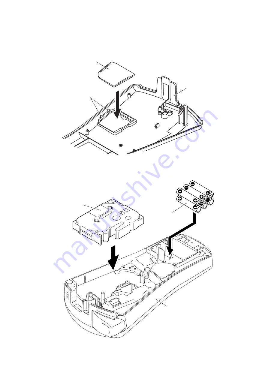
[ 12 ]Installing the Dry Cells, the Tape Cassette and the Cassette Cover

(1) Set the cassette panel to the cassette cover, and secure the cassette panel with

the two hooks.

Figure 3.1-33 Installing the Cassette Panel

(2) Set the six dry cells and the tape cassette.

Figure 3.1-34 Installing the Dry Cells and the Tape Cassette

Cassette panel

Cassette cover

Hooks

Dry cells

Tape cassette

Bottom cover

Summary of Contents for PT1090 - P-Touch - Labelmaker

Page 1: ...SERVICE MANUAL MODEL PT 1090 ...

Page 2: ... in best condition for the customer the service personnel must adequately understand and apply this manual This manual is made up of four chapters and appendixes CHAPTER I SPECIFICATIONS CHAPTER II THEORY OF OPERATION CHAPTER III DISASSEMBLY REASSEMBLY CHAPTER IV TROUBLESHOOTING Appendix 1 Main PCB Circuit Diagram Appendix 2 Key PCB Circuit Diagram Copyright Brother 2009 All rights reserved No par...

Page 3: ...I 8 2 2 Outline of Control Electronics II 9 2 2 1 Configuration II 9 2 2 2 Main PCB II 11 1 Block Diagram II 11 2 Solder Points II 12 3 Identification of Tape Cassette Type II 13 CHAPTER IIIDISASSEMBLY REASSEMBLY 3 1 Disassembly Reassembly III 2 3 1 1 Disassembly Procedure III 2 1 Removing the Cassette Cover Tape Cassette and Dry Cells III 2 2 Removing the Cutter Case ASSY and Board and Separating...

Page 4: ...he Head ASSY III 26 8 Installing the Roller Holder Release Spring the Roller Holder ASSY the Cutter Lever Spring and the Cutter Lever III 27 9 Installing the Terminal ASSY III 28 10 Installing the Terminal ASSY and the Terminal Press Cover III 29 11 Assembling the Bottom Cover and the Upper Cover and installing the Board and the Cutter Case ASSY III 31 12 Installing the Dry Cells the Tape Cassette...

Page 5: ...2 x 8 2 x 2 3 inches incl keys cutter lever and bottom feet 2 Weight Machine proper Approx 315 g 1 1 2 Keyboard 1 Entry system 52 rubber keypad 2 Key arrangement See Figure 1 1 2 1 1 3 Display 1 Display type Liquid crystal display LCD 2 Number of columns 12 columns x 1 row See Figure 1 1 2 3 Number of guidance 17 See Figure 1 1 2 57 6 mm 2 3 107 9 mm 4 2 209 4 mm 8 2 ...

Page 6: ...e of a heating element 0 18 mm wide by 0 127 mm high 4 Character size 1 1 5 Tape Cassette 1 Cassette Cartridge type TZ cassette 2 Types of tape cassettes Laminate tape cassette Non laminate tape cassette Fabric tape cassette 3 Tape size 1 1 6 Tape Cutter 1 Tape cutting Manual cutting with the cutter lever 2 Cutter unit User replaceable Size 1 2 3 4 5 16 dots 23 dots 29 dots 42 dots 56 dots Type of...

Page 7: ...I 3 Figure 1 1 2 Display and Key Arrangement USA version EUROPE version ...

Page 8: ...by 6 dry cells Optional AC adapter available AD 24ES US AD 24ES EU AD 24ES UK 2 Battery type Alkaline dry cells LR03 that come with the machine 3 Service life of batteries Will last through one 12 mm wide tape cassette and then some at room temperature and nor mal humidity 4 Automatic powering off Yes If the machine remains unused for approx 5 minutes it automatically turns itself off 5 Low batter...

Page 9: ...tions 1 3 1 Initializing When the machine power is off pressing the key with both the Function and R keys held down initializes the machine When releasing those keys be sure to first release the key and then release the Function and R keys ...

Page 10: ...nt to the selected ones out of the 64 heating elements If the selected heating element s generates heat the ink on the sandwiched ribbon will be melted and transferred to the tape producing a dot s on the tape The ink ribbon and the tape are advanced and then the next heating cycle is repeated thus forming a graphic pattern on the tape Graphic Pattern Formation While the drive motor DC motor feeds...

Page 11: ... ASSY around the shaft provided on the frame ASSY so as to press the roller holder ASSY against the thermal head side Figure 2 1 2 Holder Cam on the Cassette Cover Figure 2 1 3 Holder Cam and Roller Holder ASSY Cassette cover Holder cam Thermal head ASSY Tape cassette Roller holder ASSY Holder cam Roller holder release spring Tape feed sub roller Shaft Platen roller Holder cam Platen roller Roller...

Page 12: ...nate tape cassettes sandwiched inbetween under a uniform load by the upper and lower roller holder springs At the same time the sub roller gear becomes engaged with the tape idle gear Opening the cassette cover pulls out its holder cam so that the roller holder release spring retracts the roller holder ASSY from the thermal head providing you with enough space to replace the tape cassette Figure 2...

Page 13: ...oller gear Accordingly the sandwiched tape and ink ribbon will be advanced at the constant speed When a laminate tape cassette is mounted the sandwiched laminate tape ink ribbon and adhesive base tape will be advanced together Figure 2 1 5 Tape Feeding Mechanism Adhesive base tape Tape feed sub roller Roller holder ASSY Thermal head ASSY Transparent laminate tape Platen roller Platen idle gear Tap...

Page 14: ... ribbon take up roll in the tape cassette also rotates to take up the ink ribbon To apply proper tension to the ink ribbon between the platen and the ribbon drive cam the feed amount of the ribbon drive cam is slightly greater than that of the tape feed gear The difference between the feed speeds at the platen roller and at the ribbon drive cam is absorbed by the clutch spring which is integrated ...

Page 15: ...Y and cutter board Pressing the cutter lever pushes out the cutter blade against the cutter board cutting the printed tape coming through the cutter case ASSY and cutter board Figure 2 1 7 Tape Cutter Mechanism Tape cassette Cutter lever Cutter board Cutter blade Cutter case ASSY Tape ...

Page 16: ...lade from getting driven for safety as shown below Closing the cassette cover releases the cutter safety lock mechanism If you close the cassette cover the roller holder ASSY pivots towards the thermal head so that the cutter lever stopper does not interfere with the cutter lever Figure 2 1 8 Cutter Safety Lock Mechanism Figure 2 1 9 Releasing the Cutter Safety Lock Mechanism Cutter lever Cutter l...

Page 17: ... the cutter lever turns on the cutter sensor switch and immediately stops the DC motor This prevents the cutter blade from interrupting the tape being fed and causing a tape jam Figure 2 1 10 Cutter Jam Prevention Mechanism Cutter lever Cutter board Cutter blade Cutter sensor switch Main PCB Tape ...

Page 18: ...racters wide by one row high and it has 17 guidance indicators Motor The DC motor is a power source to advance tape and ink ribbon Thermal print head This is a thick film thermal print head which integrates a heat generator consisting of 64 heating elements vertically aligned in 180 dpi and driver circuitry Cassette sensor PCB According to the states of the four sensor switches on this sensor the ...

Page 19: ...on of the Electronic Parts AC adapter option Cassette sensor PCB CN1 LCD Thermal head red black Key PCB Cutter sensor Negative battery terminal Positive battery terminal J1 Key contacts Jumper lead wire Drive motor DC motor Main PCB ...

Page 20: ...r detector 10 LCD driver Figure 2 2 2 Block Diagram of Main PCB 12 characters x 1 row with guidance indicators LCD driver DC motor driver Thermal print head 64 dots in 180 dpi Thermal head driver Oscillation circuit Power supply circuit 3 terminal regulator AC adapter Dry cells Key contacts Cutter sensor Key PCB Voltage detector circuit Temperature sensor detector Cassette sensor Main PCB Internal...

Page 21: ...ted in Table 2 2 2 If the print head unit is replaced with a new one the soldered state may need to be changed according to the head rank code printed on the head flat cable of the new print head Table 2 2 2 Head Rank Destination Solder points 1 2 3 US Low Closed High Open High Open UK High Open Low Closed High Open GE High Open High Open Low Closed Head rank code printed on the head flat cable So...

Page 22: ...es the CPU identifies the tape width and tape cassette type as listed below Table 2 2 3 Coded Value for Identifying Tape Cassette Type 0 Switch OFF ID hole opened 1 Switch ON ID hole closed Tape width Cassette type SW2 SW3 SW6 SW7 No tape cassette loaded 0 0 0 0 3 5mm Non laminate tape cassette 0 1 1 1 6mm Laminate tape cassette 0 1 0 0 Non laminate tape cassette 0 1 0 1 9mm Laminate tape cassette...

Page 23: ...asei BG MU Location Screw type Q ty Tightening torque Main PCB ASSY SW hold plate Ribbon drive cam DC motor ASSY Motor holder Head ASSY Cassette sensor PCB ASSY Bottom cover Taptite bind B M2 6 x 6 Taptite bind B M2 6 x 6 PStite M2 x 4 CH Screw pan 1 7 x 2 5 Taptite bind B M2 6 x 10 Screw pan S P M3x7 Lock Taptite bind B M2 6 x 6 Taptite bind B M2 6 x 20 Taptite bind B M2 6 x 10 2 1 1 2 2 1 2 2 5 ...

Page 24: ... 1 Removing the Cassette Cover Tape Cassette and Dry Cells 1 Turn the machine upside down 2 Press the section A of the cassette cover to release the latch and remove the cassette cover Figure 3 1 1 Removing the Cassette Cover Cassette cover A Bottom cover Latch ...

Page 25: ...igure 3 1 2 Removing the Tape Cassette and Dry Cells 4 Release the two hooks and remove the cassette panel from the inside of the cassette cover Figure 3 1 3 Removing the Cassette Panel Dry cells Tape cassette Bottom cover Cassette panel Cassette cover Hooks ...

Page 26: ...om the bottom cover 3 Discharge the capacitor mounted on the main PCB by touching both the and terminals of the main PCB ASSY with a tweezers Figure 3 1 4 Removing the Cutter Case ASSY and Board Bottom cover Upper cover Board Screws Cutter case ASSY Screws Tweezers terminal of the main PCB ASSY terminal of the main PCB ASSY Discharging the capacitor on the main PCB ASSY ...

Page 27: ...s and remove the cassette sensor PCB ASSY from the bottom cover 7 Unsolder the two motor leads from the main PCB ASSY CAUTION When handling the PCBs put on the grounding wrist band Failure to do so might break LSIs and other electronic devices Figure 3 1 5 Separating the Bottom Cover and the Upper Cover Upper cover Main PCB ASSY Main PCB ASSY Bottom cover Cassette sensor PCB ASSY Head flat cable H...

Page 28: ...atches on the terminal press cover inward with the tip of the flat screwdriver and push down the terminal press cover Figure 3 1 6 Removing the Terminal Press Cover Bottom cover Terminal press cover Bottom cover placed upside down Latches on the terminal press cover Flat screwdriver Unlatching the terminal press cover ...

Page 29: ...wo battery terminals B and the terminal ASSY from the terminal press cover Figure 3 1 7 Removing the Terminal ASSY Terminal press cover terminal ASSY black lead terminal ASSY Releasing the terminal ASSY Battery terminals B ...

Page 30: ...III 8 4 Removing the Terminal ASSY 1 Remove the terminal ASSY from the bottom cover Figure 3 1 8 Removing the Terminal ASSY Bottom cover terminal ASSY red read ...

Page 31: ...utter lever spring from the cutter lever 3 Remove the roller holder ASSY from the bottom cover 4 Remove the roller holder release spring from the roller holder ASSY Figure 3 1 9 Removing the Cutter Lever the Cutter Lever Spring the Roller Holder ASSY and the Roller Holder Release Spring Cutter lever spring Cutter lever Bottom cover Roller holder ASSY Roller holder release spring ...

Page 32: ... the one screw and remove the head ASSY from the bottom cover CAUTION Before handling the head ASSY take care not to touch it directly by hand The head ASSY may be damaged due to the static electricity charged in your body Figure 3 1 10 Removing the Head ASSY Nut 3 M3 Screw Head ASSY Adhesive tape Bottom cover Washer ...

Page 33: ...move the double gear 2 the double gear 1 the double gear 4 the double gear 3 the tape idle gear and the P idle gear from the bottom cover Figure 3 1 11 Removing the Gears Washer Washer Double gear 2 Double gear 1 Double gear 4 Tape idle gear P idle gear Double gear 3 Bottom cover ...

Page 34: ...emove the two screws and remove the motor holder from the bottom cover 2 Remove the two screws and remove the DC motor ASSY from the motor holder Figure 3 1 12 Removing the Motor Holder and DC Motor ASSY Screws Screws Motor holder DC motor ASSY Bottom cover ...

Page 35: ...Remove the one screw and remove the ribbon drive cam and the ribbon drive gear from the bottom cover 3 Remove the ribbon clutch spring from the ribbon drive cam Figure 3 1 13 Removing the Ribbon Drive Cam the Ribbon Drive Gear and the Ribbon Clutch Spring Screw Ribbon drive cam Ribbon drive gear Ribbon clutch spring Bottom cover ...

Page 36: ...g pawls on each of three battery terminals A and push down each battery terminals A with the tip of the flat screwdriver Figure 3 1 14 Removing the Battery Terminals A Battery terminals A Locking pawls Flat screwdriver Bottom cover Bottom cover placed upside down ...

Page 37: ...e the two screws from the main PCB ASSY NOTE The main PCB ASSY consists of the main PCB the key PCB and the LCD 4 Release the two hooks of the upper cover and remove the key PCB and the main PCB 5 Release the locking pawl of the upper cover and slide the LCD to the direction of the arrow 5a NOTE Do not pull the LCD flat cable Figure 3 1 15 Removing the Cutter Sensor ASSY the Main PCB ASSY and the ...

Page 38: ...te sensor PCB ASSY leads from the main PCB ASSY Figure 3 1 16 Unsoldering the five Cassette Sensor PCB ASSY Leads Main PCB ASSY Cassette sensor PCB ASSY leads Soldering the cassette sensor PCB ASSY leads Black Yellow Red Main PCB Cassette sensor PCB ASSY leads Brown Green ...

Page 39: ...ing the Contact Sheet and the Rubber 52 Key 1 Remove the contact sheet and the rubber 52 key from the upper cover Figure 3 1 17 Removing the Contact Sheet and the Rubber 52 Key Contact sheet Rubber 52 key Upper cover ...

Page 40: ...sure that the rubber 52 key is fitted over the two positioning bosses and the seven ribs NOTE Make sure that the contact sheet is fitted over the two positioning bosses the rib and the eleven pins Figure 3 1 18 Installing the Rubber 52 Key and the Contact Sheet Contact sheet Rubber 52 key Positioning boss Positioning boss Pins Pins Pins Upper cover Ribs Ribs Rib ...

Page 41: ...onic devices 1 Solder the five cassette sensor PCB ASSY leads to the main PCB ASSY NOTE Check the wire ID colors as shown below and keep solder within the specified soldering points Figure 3 1 19 Soldering the five Cassette Sensor PCB ASSY Leads Main PCB ASSY Soldering the cassette sensor PCB ASSY leads Black Yellow Red Main PCB Cassette sensor PCB ASSY leads Brown Green Cassette sensor PCB ASSY l...

Page 42: ...rints or dust off the LCD surface with a soft cloth 4 Set the main PCB ASSY to the upper cover and secure the key PCB with the two hooks NOTE Make sure that the main PCB ASSY is fitted over the two bosses the rib and the eleven pins 5 Secure the main PCB ASSY to the upper cover with the two screws Figure 3 1 20 Installing the Main PCB ASSY Locking pawl Hooks Upper cover Positioning bosses Pins Pin...

Page 43: ...sor ASSY with the positioning hole b of the upper cover and set it 8 Pass the cutter sensor ASSY leads through the three guide grooves of the upper cover 9 Set the SW hold plate to the upper cover with the one screw Figure 3 1 21 Installing the Cutter Sensor ASSY Black Red Soldering the cutter sensor leads Cutter sensor leads SW hold plate Screw Cutter sensor ASSY Cutter sensor ASSY b Boss Pin a U...

Page 44: ...ery Terminals A 1 Set the three battery terminals A to the bottom cover and latch their locking pawls Figure 3 1 22 Installing the Battery Terminals A Battery terminals A Locking pawls Bottom cover Bottom cover placed upside down ...

Page 45: ... is the lower side 3 Insert the ribbon drive gear and the ribbon drive cam into the shaft of the bottom cover and set them with the one screw NOTE Catch the end a of the ribbon clutch spring into the groove of the ribbon drive gear Figure 3 1 23 Installing the Ribbon Clutch Spring the Ribbon Drive Gear and the Ribbon Drive Cam Screw Ribbon drive cam Ribbon drive gear Groove of the ribbonn drive ge...

Page 46: ...check that it is 20 22mm 0 05 between the shaft of the motor holder and the shaft A of the bottom cover 4 Pass the two motor leads through the guide groove a and pass the black motor lead through the guide groove b and pass the red motor lead through the guide groove c Figure 3 1 24 Installing the DC Motor ASSY and the Motor Holder Screws Screws Motor holder DC motor Motor lead Black Shaft of moto...

Page 47: ...pe idle gear into the shaft C of the bottom cover 5 Insert the double gear 3 into the shaft D of the bottom cover 6 Insert the double gear 4 into the shaft E of the bottom cover and secure their gears with the washer Figure 3 1 25 Installing the Gears Washer Washer Double gear 2 Double gear 1 Double gear 4 Tape idle gear P idle gear Double gear 3 Shaft A Shaft D Shaft E Shaft B Shaft C Bottom cove...

Page 48: ...d with the center of the two bosses of the bottom cover CAUTION Before handling the head ASSY take care not to touch it directly by hand The head ASSY may be damaged due to the static electricity charged in your body 2 Secure the head flat cable to the bottom cover with the adhesive tape Figure 3 1 26 Installing the Head ASSY Nut 3 M3 Screw Head ASSY Boss Boss Adhesive tape Adhesive tape Head flat...

Page 49: ... Set the cutter release spring to the cutter lever and hang the end c of the cutter release spring on the rib of the cutter lever 4 Set the cutter lever to the bottom cover and hang the end d of the cutter release spring on the rib of the bottom cover Figure 3 1 27 Installing the Roller Holder Release Spring the Roller Holder ASSY the Cutter Lever Spring and the Cutter Lever Bottom cover Bottom co...

Page 50: ...wn 2 Set the terminal ASSY to the bottom cover 3 Pass the terminal ASSY lead through the two guide grooves of the bottom cover Figure 3 1 28 Installing the Terminal ASSY terminal ASSY red read terminal ASSY red read Bottom cover Guide groove Guide groove terminal ASSY lead ...

Page 51: ...Press Cover 1 Set the terminal ASSY and the two battery terminals B to the terminal press cover Figure 3 1 29 Installing the Terminal ASSY Terminal press cover terminal ASSY black lead terminal ASSY black lead Releasing the terminal ASSY Battery terminals B ...

Page 52: ...bottom cover 3 Pass the terminal ASSY lead through the four guide grooves of the bottom cover Figure 3 1 30 Installing the Terminal Press Cover Bottom cover Terminal press cover Guide grooves Bottom cover placed upside down Latches on the terminal press cover Latching the terminal press cover Guide groove Guide groove ...

Page 53: ...two screws 3 Pass the yellow the red and the black leads through the guide groove a and b and pass the green and the brown leads through the guide groove c and d 4 Connect the head flat cable to the main PCB ASSY Figure 3 1 31 Installing the Cassette Sensor PCB ASSY Upper cover Main PCB ASSY Main PCB ASSY Bottom cover Cassette sensor PCB ASSY Cassette sensor leads Head flat cable Hook Hook Hook te...

Page 54: ... case ASSY to the shaft of the bottom cover and hang the hook of the cutter case ASSY on the shaft and then set the board to the rib of the bottom cover and hang the hook of the board on the rib Figure 3 1 32 Assembling the Bottom Cover and the Upper Cover and installing the Board and the Cutter Case ASSY Bottom cover Upper cover Board Screws Cutter case ASSY Screws Hook Hook Hook Hook Rib Shaft ...

Page 55: ...nel to the cassette cover and secure the cassette panel with the two hooks Figure 3 1 33 Installing the Cassette Panel 2 Set the six dry cells and the tape cassette Figure 3 1 34 Installing the Dry Cells and the Tape Cassette Cassette panel Cassette cover Hooks Dry cells Tape cassette Bottom cover ...

Page 56: ... the two latches of the cassette cover to the two positioning parts of the bottom cover and close the cassette cover Figure 3 1 35 Installing the Cassette Cover Cassette cover Bottom cover Latches Positioning parts ...

Page 57: ...ng the 1 2 3 4 5 or 6 key to proceed to the INFO submode Clock Function check mode CASSETTE KEY CUT or PRINT1 submode respectively 1 Load a tape cassette and close the cassette cover 2 Make sure that the internal memory has been initialized and the power is off For the initialization procedure refer to After completion of reassembly above 3 While holding down the Function and K keys press the key ...

Page 58: ...l head properties The LCD shows the current head rank as listed below If the print head unit is replaced with a new one the soldered state may need to be changed according to the head rank code printed on the head flat cable of the new print head Source voltage This machine shows X when driven by dry cells or via the AC adapter If the source voltage is within the specified range 7 5 0 1 VDC O will...

Page 59: ...ar as shown below by pressing the key or the 2 key Start the clock check mode by pressing the key Change the CASSETTE submode 3 key by pressing the key All guidance indicators OFF Cursor at the 1st position ON All guidance indicators ON Cursor at the 5th position from the right ON All guidance indicators ON Cursor at the last position ON The number change on the second time scale in the state of 1...

Page 60: ...judged The position of the cassette sensor is as shown below Using the switch of the 2 3 7 and 6 Do not use other than them If press the key on this checking the LCD check CST appear With LCD check CST change the checking of the cassette sensor cutter sensor switch by pressing the key The machine displays CST 1 Change the CST 2 by pressing releasing the cassette sensor 2 The machine displayed CST ...

Page 61: ...ompletion of the pressing releasing the cassette sensor change the KEY submode 4 key When the NG is judged in either sensor the machine displays CST 1 X Return to the first checking Change the CST 2 by pressing releasing the cassette sensor 2 in the state of CST 1 X Cassette sensor 7 Cassette sensor 6 Cutter sensor ...

Page 62: ...Print keys Keep pressing keys from right to left on the row And then press keys from left to right on the next row from left to right on the bottom row As shown below a key to be pressed next appears so follow the indication In this example you should press the 1 key If the pressed key works normally the key to be pressed next appears If any error is noted however the LCD shows the X together with...

Page 63: ...elow NOTE If Line Limit appears instead of Printing it means that the width of the tape cassette loaded is narrow Replace the tape cassette with a 12 mm one When printing finishes the machine displays PRN1 and enters the PRINT1 submode Cut the tape Printing Ausdruck Except the spec of GE Spec of GE OK A 1 US Print With head rank solder Without head rank solder ...

Page 64: ...out of the specified range adjust the variable resistor on the main PCB by using a flat screwdriver as shown below If the print length is out of the specified range 1 Remove the seven screws shown on page III 4 from the bottom cover and separate the bottom cover from the upper cover as shown on the next page to access the variable resistor on the main PCB 2 Rotate the variable resistor on the main...

Page 65: ... KEY submode NOTE You may skip this submode since you may check the tape cutter in any other submode With the CUT displayed the machine is in the CUT submode Press the key The machine displays Feeding feeds the tape and then displays 1 When cut the tape the power is turned off and the checking is finished Except the spec of GE Spec of GE Feeding Vor1auf ...

Page 66: ...one trouble source is found plan the most reasonable repairing procedure after reviewing the relationship between them 2 When supplying power to this machine having problems make sure that its output voltage level is 8 to 10V under no load 3 Before starting disassembly jobs first remove dry cells and discharge electrolytic capacitor C30 on the key PCB for at least 3 seconds with a resistor of 100Ω...

Page 67: ... tape cassette may be defective Is there any foreign material on the tape feed sub roller and platen roller Clean them up Does each gear on the bottom cover rotate normally when the DC motor is driven without the tape cassette Replace the roller holder ASSY Correct them with lead free solder Are the motor lead wires soldered correctly Are the motor leads broken Replace the DC motor ASSY with lead ...

Page 68: ...re the cutter sensor leads soldered correctly Replace the cutter sensor ASSY with lead free solder Replace the cutter sensor ASSY with lead free solder Replace the main PCB ASSY and regulate the motor speed Refer to Chapter III Section 3 2 PRINT1 submode ...

Page 69: ...w ones Is the printing normal Is the head flat cable connected correctly Are the thermal head and platen dirtied Is the thermal head defective End of repair Correct it Replace the thermal head ASSY If the platen or thermal print head is stained clean it with a head cleaning tape or cotton swab Black streak to be cleaned ...

Page 70: ...e tape feed sub roller gear in the roller holder ASSY may be deformed Replace the roller holder ASSY Check that the two positioning bosses provided on the bottom cover are centered in the two oblong holes in the head ASSY Replace the main PCB ASSY and regulate the motor speed Refer to Chapter III Section 3 2 PRINT1 submode Head ASSY Platen center Head surface Platen roller Positioning bosses Posit...

Page 71: ...specified one Replace the dry cells with new ones and press the key AD 24ES US AD 24ES EU AD 24ES UK End of repair Power supplied Is the machine hung up Are the positive and negative terminal ASSYs broken Replace the main PCB ASSY and regulate the motor speed Refer to Chapter III Section 3 2 PRINT1 submode Turn the machine off While holding down the Function and R keys press the key to initialize ...

Page 72: ...le Or no correct key entry is possible Any dust or foreign material on the key contacts Clean the key contacts or replace the rubber keypad End of repair Normal key entry Normal key entry End of repair The main PCB ASSY removed is defective Regulate the motor speed Refer to Chapter III Section 3 2 PRINT1 submode The contact keypad is defective Replace it ...

Page 73: ...CB ASSY is defective Replace it Does each sensor actuator on the cassette sensor PCB ASSY work normally Are the cassette sensor PCB ASSY leads soldered correctly The main PCB ASSY may be defective Replace the ASSY and regulate the motor speed Refer to Chapter III Section 3 2 PRINT1 submode Correct them with lead free solder ...

Page 74: ...A 1 Appendix 1 Main PCB Circuit Diagram NAME CODE MAIN PCB CIRCUIT DIAGRAM PT1090 LW4024001 ...

Page 75: ...A 2 Appendix 2 Key PCB Circuit Diagram NAME CODE KEY PCB CIRCUIT DIAGRAM PT1090 LW4025 001 ...

Page 76: ...Aug 2009 SM PT027 Printed in Japan ...
Reviews: