-36-
14.
BOBBIN THREAD DETECTOR
STANDARD
When the amount of the bobbin thread has decreased until the bobbin diameter is 11.4-11.8 mm, the message
"Bobbin thread is running out." should appear on the display.
ADJUSTMENT
1.
Select test mode No.10 on the touch panel.
2.
Turn the balance wheel in its normal rotation direction, align the opening of the outer rotary hook with the photo
diode, and make sure that "0.0" appears on the display.
3.
Wind the bobbin thread around the bobbin until the diameter of the bobbin is 11.4-11.8 mm, and set the bobbin
in the inner rotary hook.
4.
Loosen the screw holding the photo transistor, slightly turn the photo transistor to the left until "-.-" appears on
the display. Then turn it to the right until "0.0" appears on the display, and tighten the screw.
NOTE: Keep the area around the photo transistor and the photo diode clean.
Remove the lamp during the adjustments.
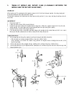
Adjustment Points
1.
Remove the needle plate before making the adjustment.
2.
After aligning the opening of the outer rotary hook with the photo diode so that "0.0" appears on the display,
the inner rotary hook (A) should contact the bracket while the photo transistor screw (B) is loosened and
tightened so that the photo transistor can be adjusted.
Summary of Contents for PC8200 SUPER GALAXIE 2000
Page 1: ...SERVICE MANUAL FOR COMPUTERIZED SEWING MACHINE PC8200 SUPER GALAXIE 2000 9 1997 ...
Page 4: ... 2 1 MECHANICAL CHART EMBROIDERY UNIT MECHANISM ...
Page 6: ... 4 3 ELECTRONIC PARTS ARRANGEMENT CHART PC 8200 Model 985 4 CONTROL SYSTEM BLOCK DIAGRAM ...
Page 16: ... 14 ...
Page 18: ... 16 ...
Page 20: ... 18 ...
Page 23: ... 21 2 LEAD WIRE ARRANGEMENT PC 8200 Model 985 ...
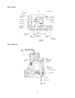
Page 53: ... 51 Main PC board Power supply unit ...
Page 54: ... 52 LCD unit Other PC boards 985 ...
Page 55: ... 53 PC8200 SG2000 H7070093 ...


