-19-
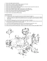
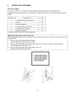
67. Attach the rear cover using the three screws.
68. Attach the needle plate assembly using the two screws.
69. Connect the five connectors, and attach the front cover using the three screws.
(When inserting the touch panel connector, confirm that the lock on the main board connector is open.)
When the front cover has been removed, always adjust the touch panel after assembling the front cover.
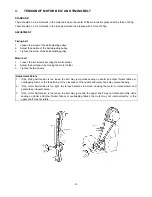
70. Insert and attach the thread guide cover.
71. Insert the base cover into the base plate and attach using the two screws.
72. Attach the belt cover using the screw, and fit the blind cap on.
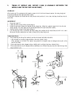
73. Attach the free arm cover using the screw.
74. Attach the face plate using the screw.
Assembly Points
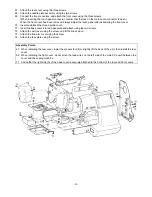
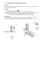
67. When installing the rear cover, lower the presser foot lifter, slightly lift the back of the unit, then install the rear
cover.
69. When installing the front cover, do not pinch the lead wires on the left side of the main PC board between the
cover and the sewing machine.
71. Check that the right side (A) of the base cover is securely attached to the bottom of the rear and front covers.
Summary of Contents for PC8200 SUPER GALAXIE 2000
Page 1: ...SERVICE MANUAL FOR COMPUTERIZED SEWING MACHINE PC8200 SUPER GALAXIE 2000 9 1997 ...
Page 4: ... 2 1 MECHANICAL CHART EMBROIDERY UNIT MECHANISM ...
Page 6: ... 4 3 ELECTRONIC PARTS ARRANGEMENT CHART PC 8200 Model 985 4 CONTROL SYSTEM BLOCK DIAGRAM ...
Page 16: ... 14 ...
Page 18: ... 16 ...
Page 20: ... 18 ...
Page 23: ... 21 2 LEAD WIRE ARRANGEMENT PC 8200 Model 985 ...
Page 53: ... 51 Main PC board Power supply unit ...
Page 54: ... 52 LCD unit Other PC boards 985 ...
Page 55: ... 53 PC8200 SG2000 H7070093 ...

