


CHAPTER 4 DISASSEMBLY AND RE-ASSEMBLY
4-7
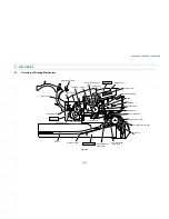
(10) Turn the cassette the correct way up and slide the two paper guides to the center of the
cassette.
(11) Remove the side guides Left and Right from the paper cassette.
Fig. 4-9
(12) Unhook the two catches (A) of the pressure plate while pulling the plastic frame outwards,
then unhook the other two catches (B) of the plate while pulling the plastic frame outwards
to remove the pressure plate ASSY.
(13) Unhook the pressure plate spring from the plastic hook to remove the two pressure plate
springs.
Fig. 4-10
Pressure plate ASSY
Pressure
plate spring
Paper cassette
(hook)
Plastic frame
Step (12)
Step (13)
(catches (A))
Step (12)
(catch (B))
Side guide L
Side guide R
Paper cassette
➀
➁
Summary of Contents for HL-1030
Page 51: ...CHAPTER 3 THEORY OF OPERATION 3 9 Fig 3 8 ...
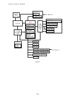
Page 53: ...CHAPTER 3 THEORY OF OPERATION 3 11 Two 32 Mbits ROMs x 16 bit are fitted Fig 3 11 HL 1270N ...
Page 122: ...CHAPTER 5 PERIODIC MAINTENANCE 5 8 ...
Page 198: ...CODE UK4352000 B512040CIR 1 2 A 20 NAME Appendix 11 Main PCB Circuit Diagram HL 1030 1240 1 2 ...
Page 199: ...Appendix 12 Main PCB Circuit Diagram HL 1030 1240 2 2 CODE UK4352000 B512040CIR 2 2 A 21 NAME ...
Page 202: ...CODE UK4361000 B512049CIR A 24 NAME Appendix 15 Main PCB Circuit Diagram HL 1250 1270N 3 5 ...
Page 205: ...Appendix 18A Engine PCB Circuit Diagram OLD CODE UK4444000 B512059CIR A 27 NAME ...
Page 206: ...Appendix 18B Engine PCB Circuit Diagram NEW CODE UK4444000 B512059CIR A 28 NAME ...
Page 207: ...Appendix 19 Network Board Circuit Diagram HL 1270N CODE LJ8107000 B512058CIR A 29 NAME ...
Page 218: ...INDEX vi ...


