


CHAPTER 4 DISASSEMBLY AND RE-ASSEMBLY
4-4
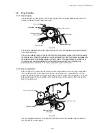
3.3
Paper Cassette
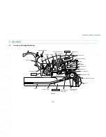
(1) Close the front cover, pull out the paper cassette from the printer and remove the paper
from the cassette.
Fig. 4-3
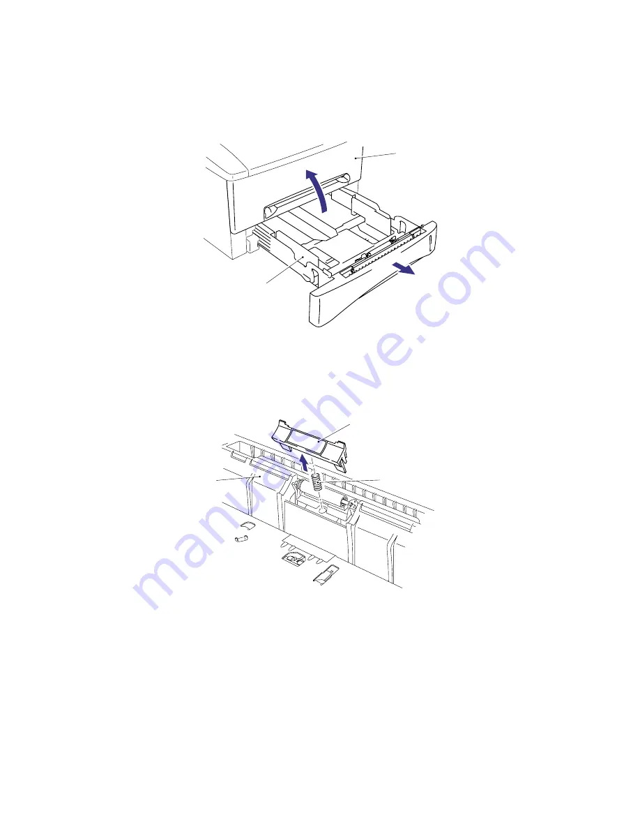
(2) Remove the separation pad holder ASSY by pulling it upwards, then remove the
separation pad spring from the paper cassette.
Fig. 4-4
Paper cassette
Paper cassette
Separation pad spring
Separation pad holder
Front cover
Summary of Contents for HL-1030
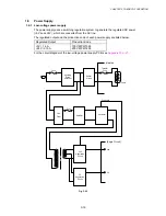
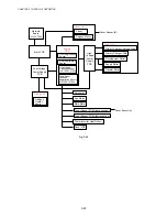
Page 51: ...CHAPTER 3 THEORY OF OPERATION 3 9 Fig 3 8 ...
Page 53: ...CHAPTER 3 THEORY OF OPERATION 3 11 Two 32 Mbits ROMs x 16 bit are fitted Fig 3 11 HL 1270N ...
Page 122: ...CHAPTER 5 PERIODIC MAINTENANCE 5 8 ...
Page 198: ...CODE UK4352000 B512040CIR 1 2 A 20 NAME Appendix 11 Main PCB Circuit Diagram HL 1030 1240 1 2 ...
Page 199: ...Appendix 12 Main PCB Circuit Diagram HL 1030 1240 2 2 CODE UK4352000 B512040CIR 2 2 A 21 NAME ...
Page 202: ...CODE UK4361000 B512049CIR A 24 NAME Appendix 15 Main PCB Circuit Diagram HL 1250 1270N 3 5 ...
Page 205: ...Appendix 18A Engine PCB Circuit Diagram OLD CODE UK4444000 B512059CIR A 27 NAME ...
Page 206: ...Appendix 18B Engine PCB Circuit Diagram NEW CODE UK4444000 B512059CIR A 28 NAME ...
Page 207: ...Appendix 19 Network Board Circuit Diagram HL 1270N CODE LJ8107000 B512058CIR A 29 NAME ...
Page 218: ...INDEX vi ...


