


CHAPTER 3 THEORY OF OPERATION
3-2
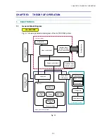
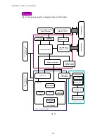
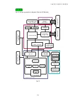
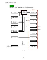
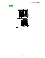
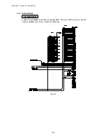
Fig. 3-2 shows a general block diagram of the HL-1250 printer.
Optional RAM (SIMM)
(max. 32Mbytes)
Optional I/F board
(Mac. RS-232C)
Expansion
memory I/O
Expansion I/O
Video control block
Engine control block
Operation block
(Control panel)
Control system
Low-voltage power
supply block
High-voltage power
supply block
Laser unit
Drive block
(DC motor)
Drum unit
Transfer block
Drum
Charging
block
External device
External device
Paper tray unit
Paper cassette
Manual feed
Fixing unit
Paper eject block
Paper feed system
Image generation system
Interface block
(Parallel / USB)
RAM 4MB
Paper dust
cleaner block
Developing
block
Toner cartridge
Fig. 3-2
HL-1250
Summary of Contents for HL-1030
Page 51: ...CHAPTER 3 THEORY OF OPERATION 3 9 Fig 3 8 ...
Page 53: ...CHAPTER 3 THEORY OF OPERATION 3 11 Two 32 Mbits ROMs x 16 bit are fitted Fig 3 11 HL 1270N ...
Page 122: ...CHAPTER 5 PERIODIC MAINTENANCE 5 8 ...
Page 198: ...CODE UK4352000 B512040CIR 1 2 A 20 NAME Appendix 11 Main PCB Circuit Diagram HL 1030 1240 1 2 ...
Page 199: ...Appendix 12 Main PCB Circuit Diagram HL 1030 1240 2 2 CODE UK4352000 B512040CIR 2 2 A 21 NAME ...
Page 202: ...CODE UK4361000 B512049CIR A 24 NAME Appendix 15 Main PCB Circuit Diagram HL 1250 1270N 3 5 ...
Page 205: ...Appendix 18A Engine PCB Circuit Diagram OLD CODE UK4444000 B512059CIR A 27 NAME ...
Page 206: ...Appendix 18B Engine PCB Circuit Diagram NEW CODE UK4444000 B512059CIR A 28 NAME ...
Page 207: ...Appendix 19 Network Board Circuit Diagram HL 1270N CODE LJ8107000 B512058CIR A 29 NAME ...
Page 218: ...INDEX vi ...


