


CHAPTER 6 TROUBLESHOOTING
6-54
Factory inspection mode
The factory inspection mode is used to check if the sensors in the printer are functioning
correctly. In the process of this inspection, the LEDs and the control panel button are also
checked.
On entering this mode, the LEDs show the status of the respective sensors as shown in the
figure below;
Toner sensor
Button unpressed
Rear registration sensor
Front registration sensor
Upper paper cassette sensor
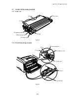
Drum
Ready
Alarm
Paper
Toner
Data
Fig. 6-12
Toner sensor
ON (The toner cartridge is installed.)
Drum LED ON
OFF (No toner cartridge is installed.)
Drum LED OFF
Rear registration sensor
ON (Paper is detected.)
Ready LED ON
OFF (No paper is detected.)
Ready LED OFF
Front registration sensor
ON (Paper is detected.)
Alarm LED ON
OFF (No paper is detected.)
Alarm LED OFF
Upper paper cassette
ON (No paper cassette is installed.)
Data LED ON
sensor (HL-1250/1270N only)
OFF (The paper cassette is installed.)
Data LED OFF
For checking more sensors, press the panel button. The LEDs show the status of the
respective sensors as shown in the figure below.
Button pressed
Paper eject sensor
Cover sensor
Lower paper cassette registration sensor
Drum
Ready
Alarm
Paper
Toner
Data
Fig. 6-13
(HL-1250/1270N only)
(HL-1250/1270N only)
Summary of Contents for HL-1030
Page 51: ...CHAPTER 3 THEORY OF OPERATION 3 9 Fig 3 8 ...
Page 53: ...CHAPTER 3 THEORY OF OPERATION 3 11 Two 32 Mbits ROMs x 16 bit are fitted Fig 3 11 HL 1270N ...
Page 122: ...CHAPTER 5 PERIODIC MAINTENANCE 5 8 ...
Page 198: ...CODE UK4352000 B512040CIR 1 2 A 20 NAME Appendix 11 Main PCB Circuit Diagram HL 1030 1240 1 2 ...
Page 199: ...Appendix 12 Main PCB Circuit Diagram HL 1030 1240 2 2 CODE UK4352000 B512040CIR 2 2 A 21 NAME ...
Page 202: ...CODE UK4361000 B512049CIR A 24 NAME Appendix 15 Main PCB Circuit Diagram HL 1250 1270N 3 5 ...
Page 205: ...Appendix 18A Engine PCB Circuit Diagram OLD CODE UK4444000 B512059CIR A 27 NAME ...
Page 206: ...Appendix 18B Engine PCB Circuit Diagram NEW CODE UK4444000 B512059CIR A 28 NAME ...
Page 207: ...Appendix 19 Network Board Circuit Diagram HL 1270N CODE LJ8107000 B512058CIR A 29 NAME ...
Page 218: ...INDEX vi ...


