5. You
ʼ
ll be given a display of the first three user presets (Fig. 7). To edit a preset,
simply touch the preset number.
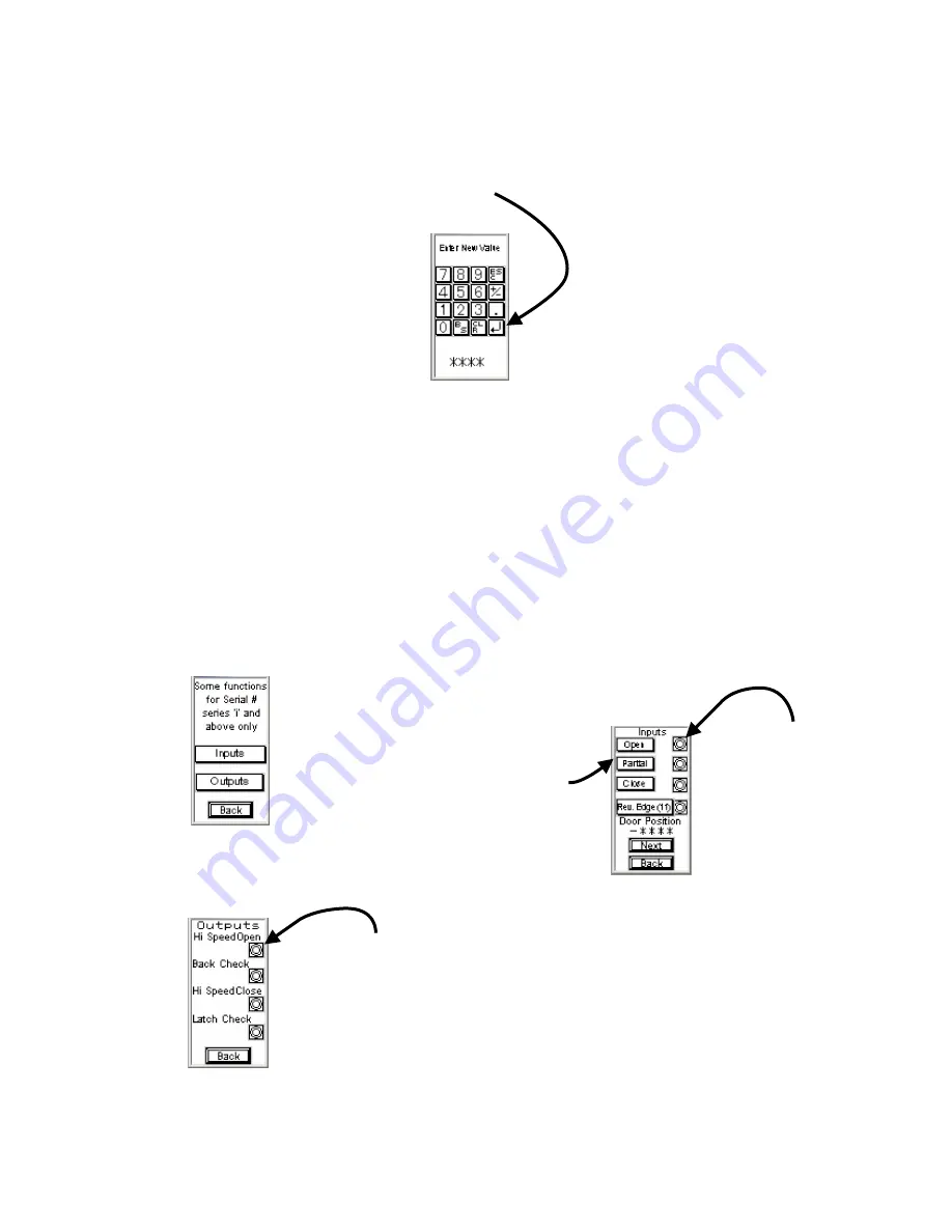
6. A keypad will then display for entering the new preset (Fig. 8). Enter the desired
value and touch the ENTER (bent arrow) key to set the value. Press ESC to
cancel and go back to the preset list.
7. Press
ʻ
Next
ʼ
(Fig. 7) to display the remaining user presets or
ʻ
Back
ʼ
to return
to the previous screen.
Note: Real Time Door Position (RTDP) is always displayed on both preset screens
Fig. 8
I/O Diagnostics for Series
ʻ
i
ʼ
Operators and Above only
Selecting the
ʻ
I/O Diag
ʼ
button from main screen (Fig. 4), will bring you to the
screen in Fig. 9.
ʻ
Outputs
ʼ
with display the screen in Fig. 11.
Fig. 9
Select
ʻ
Inputs
ʼ
to display the Input
Diagnostic Screen (Fig. 10).
Fig. 10
The buttons down the left
side, represent an actual
input to the PLC. All
standard Operator functions
can be tested using these
buttons.
The lamps down the
right side of the
screen indicate
when an actual
ʻ
hard
ʼ
input is being
read by the PLC.
E.g., if a Wall Switch or
other device is sending an
input, the applicable lamp
will be lit.
The lamps down the right side
of the screen indicate when
the PLC is sending the
corresponding Output to the
motor control.
The serial number series referred to in these instructions is the starting letter of the Operators Serial Number.
NOTE: When using the newer GT-01 Software with an older PLC, or vice-versa, the initial startup of the GT-01 may be longer than usual and/or may
display an error on the screen, it will then clear and go to the initial screen shown in either Fig. 3 or Fig. 4


