background image


KSR Series User Manual 


27 

3.3.2


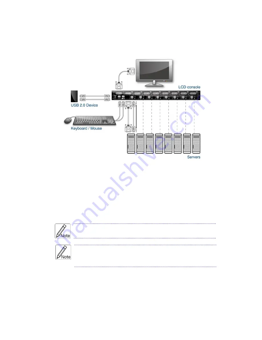
Connecting the Console 


To connect an LCD console to a computer, perform the following steps 


Figure 3-1. Connecting Diagram 


1. Turn off your computer. You should always turn off your computer before 

connecting or disconnecting a device. 

2. Connect the USB keyboard, mouse and monitor (for local console use) as well 

as other shared USB devices to the LCD console (follow your demand). 

3. Connect each of your computers to the LCD console, using the DVI video 

cable and USB (type B to type A) cable and audio cable. 


Since USB interface is hot-

pluggable, you don’t have to turn off the 

computer before making connections to the USB port.     


If you need to connect a computer with analog video port (HDB15) 

to the LCD console, you have to use a HDB15-DVI adapter for 

connector conversion. 


4. Connect the DC adapter with power cord to the DC jack on the console and then to 

a power outlet. 


Summary of Contents for KSR-11508-DVI

Page 1: ...KSR Series Single Rail LCD Console with DVI KVM Switch User Manual Rev 1 0 ...

Page 2: ...Six screws for replace long bracket The complete KSR 12008 DVI package consist of One 1U 19 rack mount console Two rails with front and rear bracket One DVI cable One USB cable USB type B to USB type A One DC power adapter One power cord One user manual CD One quick installation guide Two key Six flat screws for rail mount to console body Check to make sure that the unit was not damaged in shippin...

Page 3: ...the equipment to the power outlet 10 Please keep the power cord such a way that people can not step on it Do not place anything over power cord The power cord must rate for the voltage and current marked on the product s electrical ratings label The voltage and current rating of the cord should be greater than the voltage and the current rating marked on the product 11 All cautions and warning on ...

Page 4: ...KSR Series User Manual III User s Manual The equipment has dropped and damaged If the equipment has obvious signs or breakage ...

Page 5: ...ghtness 13 2 4 Contrast 14 2 5 Color 14 2 6 Position 15 2 7 Language 16 2 8 Recall 17 2 9 Exit 17 2 10 Power Indicator 17 3 Installation 18 3 1 Install KSR 11508 DVI 11708 DVI 11908 DVI into Cabinet 18 3 1 1 Notes 18 3 1 2 Hardware Kits Contents 18 3 1 3 Installation Steps 19 3 1 4 Replace Longer Bracket Steps For rack depth 828 1000mm 21 3 1 5 Unload Steps 21 3 2 Install KSR 12008 DVI into Cabine...

Page 6: ...Manual V 3 5 Testing the Console 28 4 KVM Switch 29 4 1 Introduction 29 4 1 1 Features 29 4 1 2 Technical Specifications 30 4 1 3 System Requirements 30 4 1 4 Cable Diagrams 31 4 1 5 Rear Panel 31 4 2 Easy Operation 32 ...

Page 7: ...h 0 255 x 0 255mm pixel pitch 20 1 inch ensures crisp images with clear definition even at high resolutions The KVM console panels are intelligent microprocessor based and have an ergonomically designed display The KVM console panels employ the latest in active matrix thin film transistor TFT technology providing crisp screen images and wide viewing angles Unlike CRT panels LCD panels are inherent...

Page 8: ...atio 550 1 Brightness White 250 cd m Center 1 point Typ Back Light Dual Lamps for Back Light Supported Colors 16M Colors 6 bit with FRC Response Time Rising Time 2 ms Decay Time 6 ms Operating System Dos Unix Linux OSX Windows XP 7 8 Server 2012 R2 Connectors PC Port Connectors 8 x DVI female 8 x USB type B 8 x 3 5mm audio jack Console Connectors 1 x DVI female 2 x USB 1 1 type A for keyboard mous...

Page 9: ...3 Keyboard Language US UK German French Spanish Italian Portuguese Dutch Swiss Belgium Swedish Hebrew Norwegian Danish Japanese Mandarin Russian Arabic Table 1 1 KSR 11508 DVI Specification Figure 1 1 KSR 11508 DVI Dimension ...

Page 10: ...6 bit with FRC Response Time Rising Time 3 8 ms Decay Time1 2 ms Operating System Dos Unix Linux OSX Windows XP 7 8 Server 2012 R2 Connectors PC Port Connectors 8 x DVI female 8 x USB type B 8 x 3 5mm audio jack Console Connectors 1 x DVI female 2 x USB 1 1 type A for keyboard mouse USB Hub Ports 2 x USB 2 0 type A device hub port Power Connector 1 x DC jack Signal Cables DVI USB A B audio cable K...

Page 11: ...KSR Series User Manual 5 Figure 1 2 KSR 11708 DVI Dimension ...

Page 12: ...ors 8 bit with FRC Response Time Rising Time 2 ms Decay Time 6 ms Operating System Dos Unix Linux OSX Windows XP 7 8 Server 2012 R2 Connectors PC Port Connectors 8 x DVI female 8 x USB type B 8 x 3 5mm audio jack Console Connectors 1 x DVI female 2 x USB 1 1 type A for keyboard mouse USB Hub Ports 2 x USB 2 0 type A device hub port Power Connector 1 x DC jack Signal Cables DVI USB A B audio cable ...

Page 13: ...KSR Series User Manual 7 Figure 1 3 KSR 11708HD DVI Dimension ...

Page 14: ... bit with FRC Response Time Rising Time 3 6 ms Decay Time 1 4 ms Operating System Dos Unix Linux OSX Windows XP 7 8 Server 2012 R2 Connectors PC Port Connectors 8 x DVI female 8 x USB type B 8 x 3 5mm audio jack Console Connectors 1 x DVI female 2 x USB 1 1 type A for keyboard mouse USB Hub Ports 2 x USB 2 0 type A device hub port Power Connector 1 x DC jack Signal Cables DVI USB A B audio cable K...

Page 15: ...KSR Series User Manual 9 Figure 1 4 KSR 11908 DVI Dimension ...

Page 16: ...pported Colors 16 7M Colors 8 bit with FRC Response Time Rising Time 7 ms Decay Time 9 ms Operating System Dos Unix Linux OSX Windows XP 7 8 Server 2012 R2 Connectors PC Port Connectors 8 x DVI female 8 x USB type B 8 x 3 5mm audio jack Console Connectors 1 x DVI female 2 x USB 1 1 type A for keyboard mouse USB Hub Ports 2 x USB 2 0 type A device hub port Power Connector 1 x DC jack Signal Cables ...

Page 17: ...KSR Series User Manual 11 Figure 1 5 KSR 12008 DVI Dimension ...

Page 18: ... tune button The panel will adjust the display size automatically and also tune the panel to its best condition Controls Description Soft power on off button Adjacent LED is lit when on Auto Auto synchronize and scale down display to any valid factory preset timings Press to scroll the function you want to adjust Press to scroll the function you want to adjust Menu To access the main menu This but...

Page 19: ...r and you will see VGA DVI 4 Use the Down and Up button to select the input source of signal 5 Press the menu button to enter 2 3 Brightness 1 Press the menu button 2 Use the Down and Up button to scroll Auto tune Input Source Brightness Contrast Color Position Language Recall Exit 3 Press the menu button to enter 4 Use the Down and Up button to adjust the brightness of the display 5 Press the men...

Page 20: ...ess Contrast Color Position Language Recall Exit 1 Press the menu button to enter 2 Use the Down and Up button to adjust the contrast of the display 3 Press the menu button to enter 2 5 Color 1 Press the menu button 2 Use the Down and Up button to scroll Auto tune Input Source Brightness Contrast Color Position Language Recall Exit ...

Page 21: ...ge Table 2 2 Icon Description 4 Use the Down and Up button to adjust the color of the display 5 Press menu to enter 2 6 Position 1 Press the menu button 2 Use the Down and Up button to scroll Auto tune Input Source Brightness Contrast Color Position Language Recall Exit 3 Press the menu button to enter And you will see Icon Description Image Pos To adjust the position of the image OSD Pos To adjus...

Page 22: ...nu button 2 Use the Down and Up button to scroll Auto tune Input Source Brightness Contrast Color Position Language Recall Exit 3 Press the menu button to enter And you will see English German French Italian Spanish 4 Use the Down and Up button to scroll 5 Press the menu button to enter ...

Page 23: ...trast Color Position Language Recall Exit 3 Press the menu button to enter and you will see Yes No 4 Select Yes button then Menu button to recall the factory setting Select No to return to the previous page 2 9 Exit Press the exit button to quit OSD menu 2 10 Power Indicator GREEN ON RED STANDBY RED SUSPEND RED OFF OSD On Screen Display ...

Page 24: ...me The cabnet depth range KSR 11508 DVI 11708 DVI 614 1000 mm KSR 11908 DVI 664 1000 mm Contact your dealer for deeper cabinet application 4 Reliable grounding of rack mounted equipment should be maintained Particular attention should be given to supply connections other than direct connections to the branch circuit 3 1 2 Hardware Kits Contents 1 Rail with front and rear bracket x 2 Please identif...

Page 25: ...w x 6 5 Key x 2 3 1 3 Installation Steps 1 Loose Not release four rear screws then adjust rear bracket to fit your cabinet 2 Install front and rear bracket on cabinet 3 Tight up four rear screws 4 Repeat step 1 3 for the other side 5 ...

Page 26: ...right rails Be careful when take out console 6 Unlock and pull rail lock switch left and right at the same time then push console to the end 7 Install three screws in rear of the console Both sides 8 Finish installation as below rail lock switch unlock lock ...

Page 27: ...racket to rear of the rail then adjust rear bracket to fit your cabinet Tight up 2 3 screws upon the length you need One is forbidden 4 Repeat step 1 3 for the other side 5 Repeat 3 1 3 step to install console 3 1 5 Unload Steps 1 Make sure the console is lock 2 Release three screws in rear of the console Both sides Rear long bracket Original bracket ...

Page 28: ...ll console out until console lock 5 Pull rail release switch and pull console out Both sides Be careful when pull out console 6 Push rail lock switch on the rail and push rail back Both sides rail release switch rail lock switch on the rail ...

Page 29: ... your dealer 2 Before installation make sure all peripherals and computer have been turned off 3 The cabinet depth range must be in 671 965 mm Contact your dealer for deeper cabinet application 4 Reliable grounding of rack mounted equipment should be maintained Particular attention should be given to supply connections other than direct connections to the branch circuit 3 2 2 Hardware Kits Content...

Page 30: ...ews then adjust rear bracket to fit your cabinet 2 Install front and rear bracket on cabinet 3 Tight up two rear screws 4 Repeat step 1 3 for the other side 5 Pull rail until it lock and keep the part A in front of the rail Both sides Then push console into left and right rails Be careful rear box loose when take out Rail ...

Page 31: ...25 console from carton 6 Pull rail release switch left and right at the same time then push console to the end 7 Install three screws in rear of the console Both sides 8 Finish installation as below Rail release switch Part A ...

Page 32: ... cases you adjust these settings by using a program or utility provided by the manufacturer of the video card Most video cards use the Windows Display Properties control panel to configure the display To open the Windows Display Properties click the right mouse button in a blank area of the Windows desktop and then select Properties The Settings tab usually lets you change the Color Palette and th...

Page 33: ...her shared USB devices to the LCD console follow your demand 3 Connect each of your computers to the LCD console using the DVI video cable and USB type B to type A cable and audio cable Since USB interface is hot pluggable you don t have to turn off the computer before making connections to the USB port If you need to connect a computer with analog video port HDB15 to the LCD console you have to u...

Page 34: ...rols to adjust the image see note below or press the Auto button on the left or underneath of the panel If the unit does not power on when the panel is pulled up try to push the power on off button on the left of the LCD panel to power up the unit You can adjust the horizontal and vertical position contrast and brightness to better suit your video card and your personal preference Refer to Chapter...

Page 35: ...ight need to use a hotkey preceding sequence other than two scroll locks we also offer five key alternatives for free configuration 4 1 1 Features 8 port DVI USB KVM switch with audio switching and 2 x USB 2 0 hub ports TMDS specifications compliant VESA DDC2B emulation TMDS signal pass through HDCP specifications compliant USB Keyboard and mouse support USB 2 0 Specification compliant DVI Single ...

Page 36: ...1 x DVI female 2 x USB 1 1 type A for keyboard mouse USB Hub Ports 2 x USB 2 0 type A device hub port Power Connector 1 x DC jack PC Selection Hotkey Scan Delay Time 5 100 sec programmable Table 4 1 Technical Specifications 4 1 3 System Requirements Model No KSR 11508 DVI 11708 DVI 11908 DVI 12008 DVI Computer side 8 x DVI male to DVI male 8 x USB type B to USB type A cable 8 x audio cable Table 4...

Page 37: ...type B to USB type A cable Figure 4 2 USB Cable 3 5 mm Audio Cable Figure 4 3 Audio Cable 4 1 5 Rear Panel Figure 4 4 Rear Panel Local Console DVI Port Audio Port for Connect Host USB type B Port for Connect Host DVI Port for Connect Host Local Console Keyboard Mouse Ports USB type A USB Hub Ports USB type A DC Power Jack ...

Page 38: ...ollLock H then two beeps will signal readiness for new preceding sequence selection or Press and hold down the last front panel button Button 2 or Button 4 until you hear two beeps then release the button 2 Select and press the key you would like to use as your preceding sequence SCROLL LOCK CAPS ESC F12 or NUM LOCK keys are available for selection and you ll hear a beep for selection confirmation...

Page 39: ...Hub port control if PC hub port control binding is enabled Select Audio Channel 3 Joint select PC port audio if binding is enabled ScrLk ScrLk A y y is a top row number key y 1 8 for audio channel no Select the active Audio channel Joint select PC audio channel if binding is enabled Bind PC Hub Port Control Switching 2 Default ScrLk ScrLk Z Enable the binding of PC port and hub port control switch...

Page 40: ...the next higher connected PC channel Joint select PC hub port control audio if binding is enabled Previous PC channel ScrLk ScrLk Backspace Toggle between the previous channel and current channel Beep Sound On Off ScrLk ScrLk B Toggle on off the beep sound while auto scanning Define Hotkey Preceding Sequence ScrLk ScrLk H y y SCROLL LOCK CAPS ESC F12 or NUM LOCK Select the hotkey preceding sequenc...

Page 41: ...sequence key configuration please refer to Quick Installation Guide 2 When the binding of PC USB hub port control switching is enabled by the hotkey sequence ScrLk ScrLk Z any PC and hub port control switching are bound together To remove this binding use the hotkey sequence ScrLk ScrLk X 3 When the binding of PC Audio switching is enabled by the hotkey sequence ScrLk ScrLk Q any PC and audio swit...

Reviews: