
G730-Install-IG100 Installation Guide
Brocade
®
G730 Switch Hardware Installation Guide
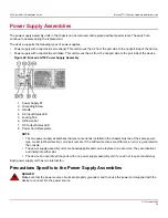
Monitoring the Device
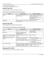
The power-on self-test (POST) performs diagnostic tests every time the device is powered on, rebooted, or reset. The
LEDs on the device indicate system activity and status.
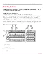
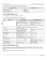
Interpreting Port-Side LEDs
System activity and status can be determined through the activity of the LEDs on the switch.
There are 96 bicolor LEDs (green/amber) for the first 96 SFP+ ports and 16 tricolor LEDs (green/amber/white) for the
SFP-DD ports. The last set of LEDs pulse once in white before indicating the FC port status in green or amber. All
functionality pertaining to the green/amber colors for the last 16 LEDs remains the same as the first 96 LEDs.
The LEDs have three possible states: no light, a steady light, and a flashing light. Flashing lights may be slow, fast, or
flickering. The lights are green or amber.
Sometimes, the LEDs may flash any of the colors during boot, POST, or other diagnostic tests. This flashing is normal;
it indicates a problem only if the LEDs indicate an unhealthy state after all boot processes and diagnostic tests are
complete.
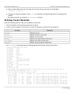
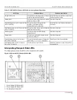
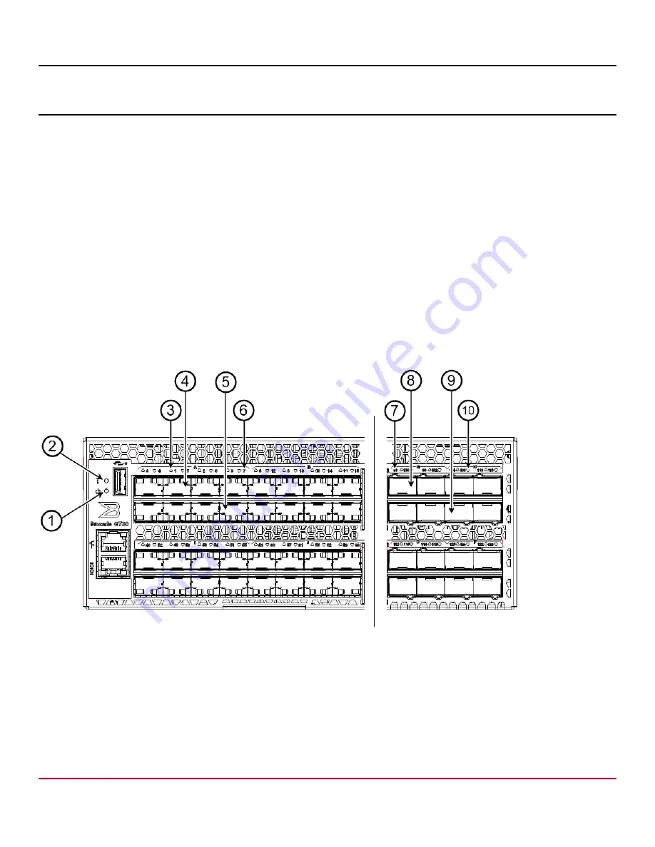
Figure 38: Brocade G730 Port-Side LEDs
1. System Power LED
2. System Status LED
3. SFP+ (Upper) Port 1 Status LED
4. SFP+ (Upper) Port 1
5. SFP+ (Lower) Port 7
6. SFP+ (Lower) Port 7 Status LED
7. DD (Upper) Ports 96 and 97 Status LED
8. DD (Upper) Ports 96 and 97
G730-Install-IG100
60
Summary of Contents for Brocade G730
Page 94: ......


