
G730-Install-IG100 Installation Guide
Brocade
®
G730 Switch Hardware Installation Guide
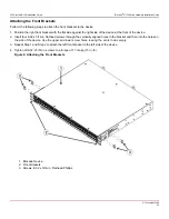
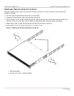
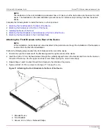
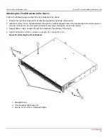
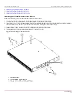
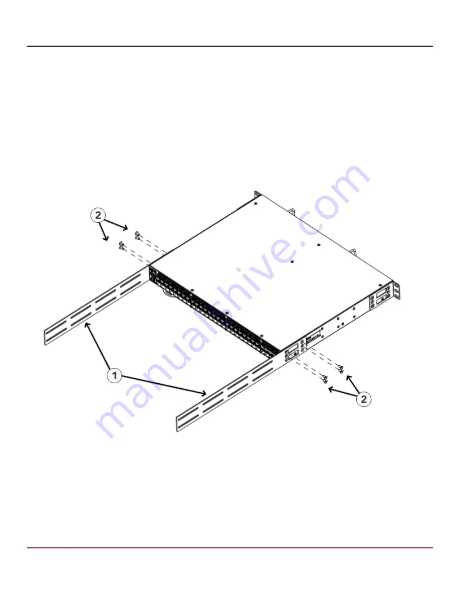
Attaching the Extensions to the Front of the Device
Perform the following steps to attach the extension brackets to the front of the device. You can use medium or long
extension brackets for this task, depending on your rack depth.
1. Select the proper length extension bracket for your rack depth.
2. Position the right extension bracket along the side of the device.
3. Insert four 8-32 x 5/16-in. flathead screws through the vertically aligned holes in the extension brackets and then into
the holes on the side of the device. Use the upper and lower screw holes, leaving the center holes empty.
4. Repeat Steps 2 and 3 to attach the left front extension bracket to the left side of the device.
5. Tighten all the 8-32 x 5/16-in. screws to a torque of 17 cm-kg (15 in.-lb).
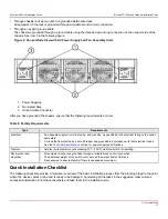
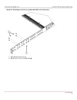
Figure 12: Attaching the Extensions to the Device
1. Extensions
2. Screws, 8-32 x 5/16-in. Flathead Phillips
G730-Install-IG100
29
Summary of Contents for Brocade G730
Page 94: ......


