TM
GE60 Installation Manual
580-00505, rev 0.4
26 of 30
PRELIMINARY
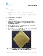
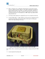
10. Remove the plastic cover on the back of the radio that is secured with a cap bolt.
Look to see that the “Link Up” LED is lit. This LED is lit when the two radios are
aligned and passing data to one another. The link may still need be optimized via
additional movement of the radio up and down and left and right; however, there is
no need to proceed to the “Fine Alignment” or “BER voltage” steps detailed below
unless this LED is lit.
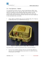
11. If desired, perform optional Fine Alignment (Section 3.9) on both sides of the link.
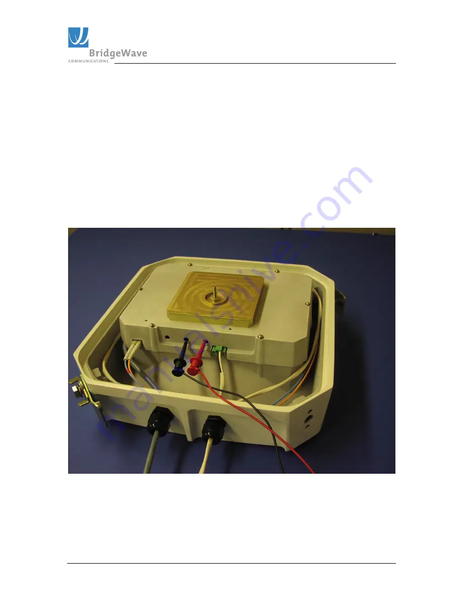
12. Check the BER voltage. 3.3VDC indicates error free link. Note--alignment must be
completed on both sides of the link and “Link Up” LED must be lit solid green
before valid voltage readings can be made.
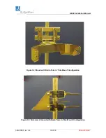
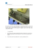
Figure 3-10: Proper placement of voltmeter cables to check Pre-FEC BER
Note: Black cable is connected to ground and red cable is connected to Pre-FEC BER
pin
12. Securely tighten all mounting bolts.

