TM
GE60 Installation Manual
580-00505, rev 0.4
25 of 30
PRELIMINARY
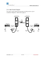
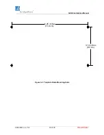
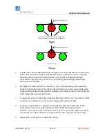
Radio at far end of link
The alignment aids need to be in a straight line.
Target, other radio, is placed at top of middle aid.
Right
Radio at far end of link
Aiming Too low
Wrong
5.
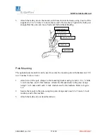
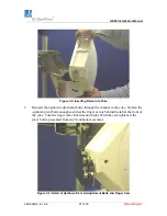
Tighten the left/right adjustment bolt enough to prevent accidental movement of the
radio. This is the bolt on the mount bracket, closest to the wall or pole. Verify the
radio has not moved in left/right direction. As this bolt is tightened up/down
movement of the radio may occur due to the seating the mounting bracken and
radio yoke seat together.
6.
Re-adjust the radio up/down, as necessary, due to the tightening of the mounting
bracket. Tighten the lower bolts (below the up/down pivot bolts) on the radio yoke,
being careful not disturb the up/down pointing of the radio. Once the lower bolts are
tight, tighten the up/down pivot bolts.
7.
Connect DC power to the radio, check that the Power LED is lit. If the Power LED
is not lit, use voltmeter to verify correct voltage and polarity at radio.
8.
Connect Tx & Rx fibers to the radio and check that the Fiber LED is lit. If the
Fiber LED is not lit, swap the position of the Tx & Rx fibers and recheck.
(NOTE: In the event a fiber loopback cable is used on one of the radios in order to
test the link, the Fiber LED will not light until the link is aligned and operating)
9.
Repeat steps 1 through 8 on other side of link.

