TM
GE60 Installation Manual
580-00505, rev 0.4
27 of 30
PRELIMINARY
3.9 Fine Alignment --
Optional
The fine alignment procedure uses Receive Signal Strength Indication (RSSI) voltage
generated by the radio’s receiver. Since this voltage reacts to the power of the received
signal, it is not influenced by the machining/manufacturing tolerances seen with
mechanical parts. While procedure can yield an improvement of up to 2 dB in Link
Budget when performed on both sides of the link, only those links with path lengths near
the maximum length will see any benefits.
1.
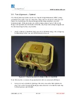
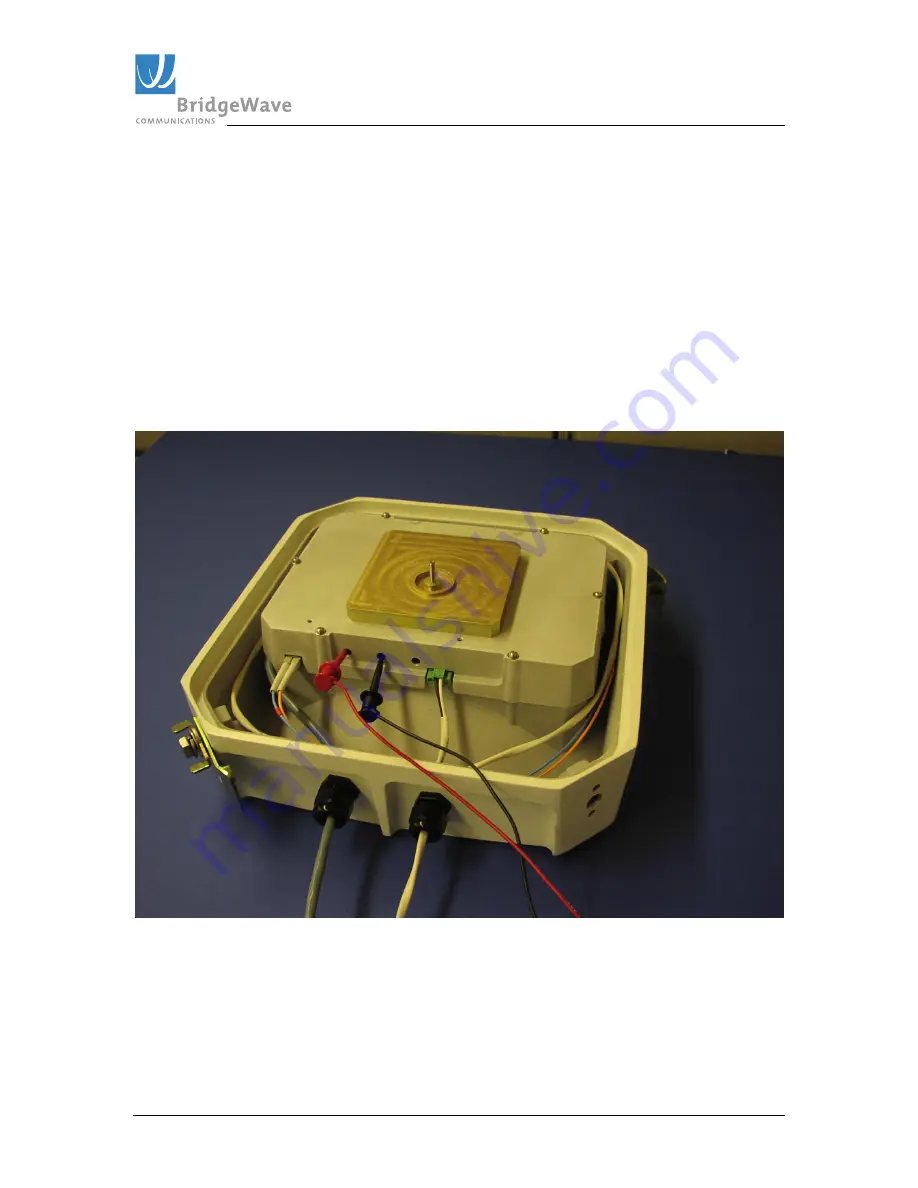
Attach voltmeter to the RSSI voltage pins. Note the RSSI voltage. The voltage may
be fluctuating; in this case, note the maximum value seen.
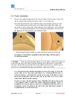
Figure 3-11: Proper placement of voltmeter cables to check RSSI
Note: Black cable is connected to ground and red cable is connected to RSSI pin
2.
Using care not to disturb the pointing of the radio, loosen the bolts tightened in
steps 5 & 6 of the Visual Alignment procedure (Section 3.8) so that the radio may
be tilted up/down and left/right.

