


6
brentwheels.com
BRENT® IE AND IE-X
POTTER’S WHEELS LEG INSTALLATION
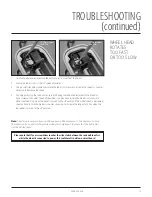
The wheel has an on/off switch, a fuse, and on
some models, a reversing switch located on the
right side of the wheel. Make sure the foot pedal
is in the “off” position before turning your power
switch on.
Occasionally, due to minor voltage variations, you
may need to adjust the foot pedal to achieve an
optimal calibration to your electrical environment.
(see Troubleshooting, pages 15-17)
Once you have carefully removed your wheel
from the carton, you will find it is shipped in its
table-top configuration. It comes equipped with
a 9-foot cord for versatility.
1. Position the wheel on its back edge with the bottom facing you.
Do not allow the wheel to tip over as it may damage the wheel
head assembly.
2. Remove the end caps from the leg stubs of the wheel (this allows
the legs to be inserted into the leg stubs). Remove the foot pedal
and the three (3) legs from the attached box.
3. Insert a leg into one of the two bottom
leg cylinders of the main assembly until
fully seated. Using the
5
/
16
" allen wrench
(provided) turn both set screws until they
make contact with the leg, then tighten each
screw another ¼ turn.
NOTE: Each leg comes with a cap plug
installed in the bottom. These plugs may
loosen during shipping, to reseat, tap them
lightly with a hammer.
4. Repeat step 3 for the remaining two legs
inserting the top leg last.
5. With the legs fully seated, the wheel is at the
industry standard height. If you prefer, you
may raise the wheel height by loosening the
set screws and pulling the legs out to the
desired length. Then retighten the set screws
as described in step 3.
NOTE: Ensure that all three (3) legs are set
to the same length so the wheel will sit level.
SHIPPED IN
TABLE-TOP
CONFIGURATION
CHANGING TO
FLOOR MODEL
CONFIGURATION
USING YOUR
NEW WHEEL