


15
PariX
2
ENGLISH
Rev.2.0
FIG. 15
4
5
6
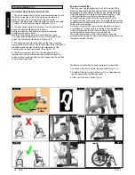
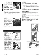
ADJUSTING THE CALF PAD
(Fig 15).
The calf pad can be adjusted as
follows:
Height: Open bolt (4) and move
the clamping piece to the desired
position. By rotating the clamping
piece also the angle can be
adjusted.
Depth: Open bolt (5) and move the
calf pad into the desired position.
Width: Open bolt (5) and position
the spacers (6) behind the pad, to
get the desired position.
WARNING!
•
Keep hands clear of the adjustable mechanism between
the frame and the movable parts of the foot rest, while
elevating or lowering the footrest.
•
Always make sure that the fasteners are secure.
•
The foot rests must not be used to lift or to carry the
wheelchair.
•
Risk of trapping fingers! When moving the foot rest up or
down, do not put your fingers in the adjusting mechanism
between the moving parts of the foot rest.
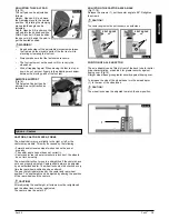
AMPUTEE SUPPORT
(Fig.16).
The Amputee Support can be
adjusted in every direction as
required.
FIG. 16
Options - Castors
CASTORS, CASTOR PLATES, FORKS
The wheelchair may veer slightly to the right or left, or the
castors may wobble. This may be caused by the following:
• Forward and/or reverse wheel motion has not been set
properly.
• The castor angle has not been set correctly.
• Castor and/or rear wheel air pressure is incorrect; the wheels
do not turn smoothly.
The wheelchair will not move in a straight line if the castors have
not been properly adjusted. Castors should always be adjusted
by an authorised dealer. The wheel locks must be checked every
time the rear wheel position has been altered.
The seat height is determined by the castor and rear wheel
position. The seat height can be adjusted by altering the position
of the rear wheels and the castors
CAUTION!
After adjusting the seat height, all screws must be re-tightened
and the wheel lock must be readjusted.
The castors must be set at 90
°
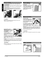
ADJUSTING THE CASTOR AXLE ANGLE
(Fig.17-18).
Release the screws (1), set the castor angle to 90
°
. Retighten
the screws.
CAUTION!
The castor angle must be set the same on both sides.
POSITION OF AXLE ADAPTOR
The axle adaptor can be fitted in front of the back tube for better
drive characteristics, or behind it for greater security against
tipping over, (Fig.19).
A larger wheel base gives greater security against tipping over.
To increase the size of the wheel base turn the axle adaptor,
(1), to the rear of the wheelchair.
CAUTION!
The wheel locks must be adjusted to match the new position.
SEAT ANGLE
= 0
°
FIG. 18
SEAT ANGLE
= 3
°
FIG. 17
1
1
FIG. 19
1


