Assembly Instructions
/
Parts List
/
Troubleshooting
/
FAQ
/
Tips
/
Warranty
BREDABEDS
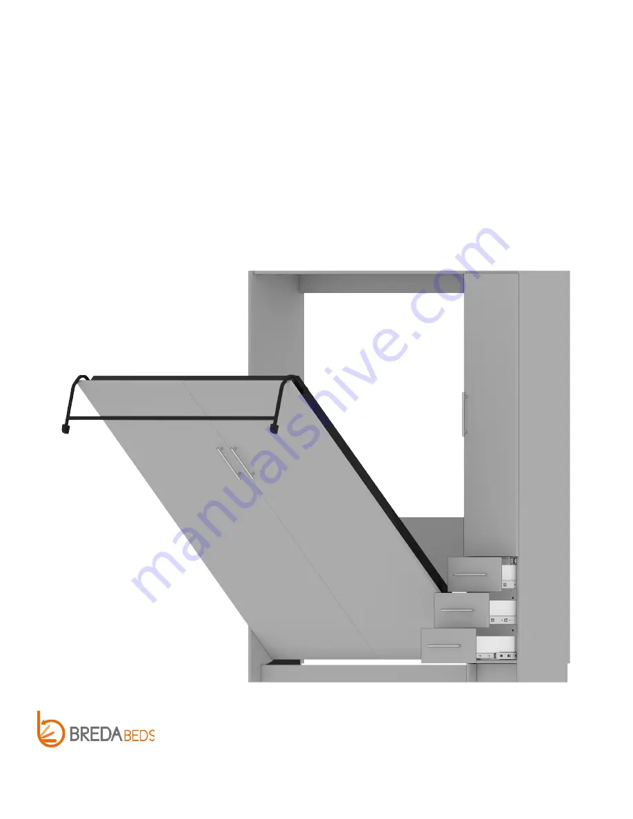
MURPHY BED
W/ RIGHT HUTCH
INCLUDING URBAN AND METROPOLITAN COLLECTION MURPHY BEDS
Web:
https://bredabeds.com
Email:
[email protected]
Telephone:
1-855-466-4781
REVISION: E|3.7
1127 N 39th Street
Nampa, Idaho 83687
MB1-HR
MAY 2020


