background image

Page 30/42

MULCHING MOWER MASTER SERIES | User manual

February 2021

7.4

Adjusting the mulcher mower unit

Attach the mower unit to the tractor on a flat, level surface. Use an adjustable top link.
Lower the three-point mounting to its lowest position.
Adjust the length of the top link with the rear roller in contact with the ground, such that the lower edge on the side 
of the mower unit is parallel to the ground.
The skids, the rear roller and the three-point mounting should be adjusted such that the distance between the 
cutting tools and the ground is at least 50 mm.
Adjust the height of the roller to increase or decrease the blade clearance as required.

Operate the mower unit at a maximum PTO speed of 540 rpm.

7.5

Adjusting the drive belts

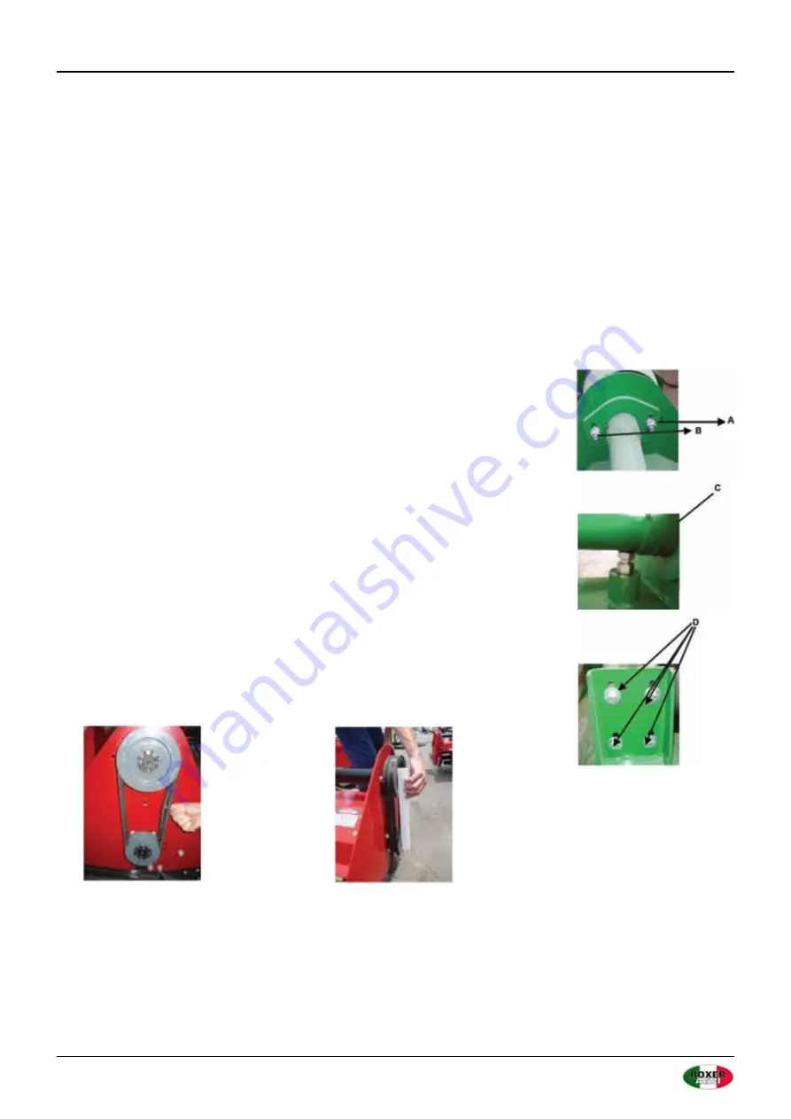
The correct drive belt tension is achieved by adjusting the belt pulleys. The pulleys 
can be adjusted via the drive train height adjustment.
To do this, loosen screws A and B and loosen the height adjustment lock nut C and 
the screws D holding the PTO transmission.

Adjust the drive belt tension. The correct belt tension is reached when the belt can 
be deflected 10 mm max. in the center.
Align the transmission and drive shaft such that the drive shaft is parallel to the 
body.

Use a spirit level or other tool to check that the pulleys are perfectly vertically 
aligned, i.e. they must be vertically parallel above each other. If they have moved, 
contact the seller for technical support. The pulleys are secured by an expander 
cone on the respective shaft and can be moved horizontally after loosening the 
expander cone.

10 mm deflection max.

Check the vertical alignment of the pulleys using a 

spirit level. The pulleys must be absolutely parallel.

Summary of Contents for MASTER 155

Page 1: ...MULCHING MOWER MASTER SERIES USER MANUAL P de Heus en Zonen Greup B V Stougjesdijk 153 3271 KB Mijnsheerenland The Netherlands Tel 31 0 18 66 12 333 E mail info boxeragri nl...

Page 2: ...MULCHING MOWER MASTER SERIES User manual February 2021 EN ENGLISH TRANSLATION OF THE ORIGINAL MANUAL...

Page 3: ...ICATIONS 12 5 INSTALLATION INSTRUCTIONS 13 6 IMPORTANT NOTES PRIOR TO COMMISSIONING 26 7 COMMISSIONING 27 7 1 Fitting to the tractor 27 7 2 Fitting the drive train 29 7 3 Adjusting the working height...

Page 4: ...mounts but can also be operated on Cat II by means of adapter sleeves 1 2 Symbols This brochure contains three graphical safety symbols highlighting the level of danger or important information WARNI...

Page 5: ...egible labels immediately WARNING Control and servicing may only be carried out after the operating and servicing manual has been carefully read with the prime mover switched off and the ignition key...

Page 6: ...bjects Do not stand next to the machine do not climb over or approach the machine Keep a safety distance of at least 70 m to the machine WARNING Do not approach the machine under any circumstances whe...

Page 7: ...Cutting WARNING Hot surface Keep an appropriate distance WARNING Only remove or open protection devices once the belts no longer move WARNING HAZARD to the upper and lower extremities Keep an appropr...

Page 8: ...Page 8 42 MULCHING MOWER MASTER SERIES User manual February 2021 Wear protective clothing Grease nipple...

Page 9: ...weight to use a different speed than 540 RPM for the PTO to use the machine on very stony soil to use the machine on a very steep slope to approach the machine wearing unsuitable working clothes to c...

Page 10: ...sk to protect eyes and face Safety helmet Safety shoes Only wear personal safety equipment in a good condition complying with the respective legal regulations 3 6 General safety instructions ALWAYS PA...

Page 11: ...e equipment inappropriately or if they are in poor condition For example do not use pipe wrenches instead of wrenches Once you have completed any servicing or repair work ensure that no equipment wipe...

Page 12: ...PTO speed rpm Recommended power HP Category Weight kg Blades MASTER 155 155 540 30 65 CAT I 367 24 MASTER 175 175 540 35 65 CAT I 412 28 MASTER 200 200 540 55 70 CAT I II 460 32 MASTER 220 220 540 75...

Page 13: ...all screws and nuts for correct seating during assembly When opening the wooden crate pay attention to the sharp edges on the closing mechanisms When you start assembling the machine please pay atten...

Page 14: ...rts and set to one side for later use Check the delivery for completeness see figures 5 to 8 Note There may be more screws nuts washers etc in the transportation crate than are needed for initial inst...

Page 15: ...attaching the 3 point bracket check the position of the 4 grease nipples on the underside of the hydraulic lateral shifter The grease nipples must point to the outside because otherwise the grease gu...

Page 16: ...eral shifter to the mulcher housing The image shows the left side as an example It is important to mount the reinforcing shims from the inside of the housing For convenience the flail mower can be jac...

Page 17: ...lateral shifter for clearance no hydraulic lines etc in the way before using the flail mulcher for the first time Remove the protective caps from the hydraulic hoses only when using the machine 6 Att...

Page 18: ...lley alignment The pulleys must be vertically aligned i e they must be vertically parallel above each other The correct pulley alignment is adjusted via the Shaft guide Figure 20 Tensioning device Fig...

Page 19: ...that the shaft has sufficient distance to the housing and does not drag on the housing Figure 26 shows the correct drive belt tension The deflection depth of the belt may not exceed 10 mm because oth...

Page 20: ...ary 2021 9 Inspect pulleys for secure seating Please ensure that the eight Allen screws on the pulleys are tightened and correctly connected to the drive shaft Figure 27 and the flail shaft Figure 28...

Page 21: ...ient transmission oil Unscrew the filler plug and inspection plug and remove them Then fill the transmission and drivetrain with oil until the oil can be seen at the inspection port We recommend SAE 8...

Page 22: ...ke off with grease nipple Please correctly lubricate both sides of the power take off Figure 34 shows one of the four grease nipples on the hydraulic lateral shifter Here it can be seen why the grease...

Page 23: ...d on the outside and the nuts and washers on the inside Please note that the nuts do not have to be screwed to the lower flail shaft because they are generally welded on from the inside Finally insert...

Page 24: ...2021 13 Fit power take off guard Attach the guard to the transmission as shown in Figure 38 using the 4 screws 4 spring washers and 4 washers Fig 38 Power take off guard Fig 39 Reversible bolt with re...

Page 25: ...ning 16 Transmission lifting eye To lift the transmission a lifting eye can be screwed to the transmission Figure 42 The lifting eye is used exclusively for lifting the transmission Please ensure you...

Page 26: ...haft a closed bearing has been installed In this case no oil fill is necessary Examine all screws for tightness and retighten if necessary Adjust the black universal shaft guard on the transmission Th...

Page 27: ...e mower unit safely Using the mower unit on an improperly equipped tractor or tractor of the wrong size can cause damage to the tractor and or mower unit and endanger the operator and bystanders Befor...

Page 28: ...parallel to the ground This reduces the pressure on the drive and extends the machine life WARNING Pay attention to the position of the tractor s front wheels when the unit assembled and raised If th...

Page 29: ...ach other with the three point hydraulics in any position When the universal shaft is fully pushed together there should be at least 20 mm clearance between each profiled end and the opposing profiled...

Page 30: ...s The correct drive belt tension is achieved by adjusting the belt pulleys The pulleys can be adjusted via the drive train height adjustment To do this loosen screws A and B and loosen the height adju...

Page 31: ...R SERIES User manual CAUTION If the belts are incorrectly aligned the belts will be destroyed within a very short time This damage and the consequences of this damage are not covered by the statutory...

Page 32: ...nd highways Do not exceed a speed of 25 kph Adjust speed to suit the road conditions and reduce speed considerably on roads or tracks with potholes as this could otherwise damage the tractor or the mo...

Page 33: ...ixing with the grease thereby reducing the lubrication effect When adding oil or replacing the oil we recommend using the same oil in order to avoid mixing oils with different properties Stop the engi...

Page 34: ...n Lubricant Remark PTO Universal joints Cross joints Every 8 h Yes I NLGI 2 grease PTO Profile tube Every 8 h Yes I NLGI 2 grease PTO Retaining pin Every 8 h Yes I Oil Screw inspection Tight fit Initi...

Page 35: ...10 1 Master MASTER No Article no Part no Name Quantity Remark 1 801680014 EFGCM120 014B Mount 1 2 802480066 EFAG140 014 Lower link bolt 2 EFGCHMZ105 175 2 1 702480065 EFAG140 114A Connecting sleeve 2...

Page 36: ...0 00 123 Protective plate bar 200 1 EFGCHMZ200 11 9 701010007 EF220 00 123 Protective plate bar 220 1 EFGCHMZ220 12 508011473 GB879 1 4x25 Cylindrical pin 2 13 700920108 EF100 00 122 Protective plate...

Page 37: ...0 Lock nut 4 40 509010008 GB1152 M8x1 Grease nipple 4 41 515010001 REACH04 35X60 Cover lock 2 42 701160006 EFG120 105A Small pulley three track 1 EFGCHM105 175 42 1 701160034 EFG120 105B Small pulley...

Page 38: ...150 024 Scraper 155 1 EFGCHMZ155 61 6 801200008 EFG160 024 Scraper 165 1 EFGCHMZ165 61 7 801210008 EFG170 024 Scraper 175 1 EFGCHMZ175 61 8 801130012 EFG200 024 Scraper 200 1 EFGCHMZ200 61 9 801130013...

Page 39: ...GB96 1 10 Large washer 4 75 506030036 GB93 10 Spring washer 4 76 501011112 GB5783 M10x25 Screw M10x25 8 77 702420030 EF100 00 177 Input shaft cover 1 78 802000001 EFGCHMZ100 011 Housing 105 1 EFGCHMZ...

Page 40: ...00 1 EFGCHMZ200 220 4 506030037 GB93 12 Spring washer 4 5 505011445 GB70 1 M12x35 Screw M12x35 4 6 507010086 GB1096 A 10x8x40 Spring washer 1 7 701220003 EFGC100 133A Shaft EFGC105 115 1 EFGCHMZ105 11...

Page 41: ...EFGCHMZ105 175 8 1 702080002 AG14 01 C05 G2 Gear wheel 1 EFGCHMZ200 220 9 703340013 NFG RCA 80X10 80X10 Cover 2 10 701240041 GC175 01 C04A Input shaft 1 11 702480003 AG14 01 C03 Cover 1 12 705290211...

Page 42: ...adpleegd UNI EN 13524 2004 EN 754 UNI EN 1553 2001 Auf dass sich diese Erkl rung bezieht den einschl gigen grundlegenden Sicherheit und Gesundheitsanforderungen EG Richtlinie 2006 42 CE UNI EN 13524 2...

Reviews: