background image

7-1

Bosch Security Systems   07/14   BLCC610I

SEC TION 7


Input Programming

T

he control panel is capable of controlling up to 144 
inputs in either hardwire and/or wireless configuration. 

Each input can have its own unique name up to 20 
characters to identify it on the system for display and 
reporting purposes. 

Under the commands menu you are able to view the 
status of any input, bypass a zone, define which zones will 
operate in chime mode, define which zones operate in 
part 2 mode and reset smoke detectors.

There is a command called 'Zone Array' that allows the 
installer to view the condition of inputs in banks of 16. 
This is extremely helpful when commissioning a system 
or fault finding.

There are numerous configurations for each hardwire 
input. The end of line resistor can be configured to 
eliminate the need to change the end of line resistors on a 

job when doing a change over.  Input zones can be setup 
as alarm only, alarm + tamper or even split end of line. 

For normally open contacts the system is wired exactly 
the same as for normally closed but there is an option 
provided that inverts the sealed state of a zone.

When arming the system, all zones will be tested by default 
and you may wish to turn this option off for certain zones 
so that you don’t continually alert the operator during 
arming. 

The sensor watch feature lets you monitor zones to ensure 
that they are working and detecting movement within a 
determined programmable period.

Zones by default can be bypassed and you should disable 
this option for zones you don’t want to be able to bypass, 
for example 24hr, fire, holdup or panic zone types.

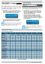
ZO N E  A S S I G N M E N TS

Zone Assignment Table

Module 

Number

Address Setting

Zone

 Numbers 

(Single EOL)

Zone 

 Numbers 

(Alarm+Tamper 

EOL)

Single or Alarm 

+ Tamper EOL 

With  

CM707B  Module

Zone  

Numbers 

(Split EOL)

SW1 SW2 SW3 SW4 SW5

Control Panel

1 - 8

1 - 8

N/A

1 - 16

1 =

OFF OFF OFF OFF OFF

17 to 24

17 to 24

17 to 24

17 to 32

25 to 32

2 =

ON OFF OFF OFF OFF

33 to 40

33 to 40

33 to 40

33 to 48

41 to 48

3 =

OFF ON OFF OFF OFF

49 to 56

49 to 56

49 to 56

49 to 64

57 to 64

4 =

ON ON OFF OFF OFF

65 to 72

65 to 72

65 to 72

65 to 80

73 to 80

5 =

OFF OFF ON OFF OFF

81 to 88

81 to 88

81 to 88

81 to 96

89 to 96

6 =

ON OFF ON OFF OFF

97 to 104

97 to 104

97 to 104

97 to 112

105 to 112

7 =

OFF ON ON OFF OFF

113 to 120

113 to 120

113 to 120

113 to 128

121 to 128

8 =

ON ON ON OFF OFF

129 to 136

129 to 136

129 to 136

129 to 144

137 to 144

Table 20: Zones Assignments  To Modules

Summary of Contents for SOLUTION 6000

Page 1: ...Solution 6000 Security System Installation Guide EN Security Systems ...

Page 2: ... acceptance of responsibility for the correct operation of that device under all operating conditions This equipment shall not be used in any manner that could constitute a nuisance to other Telecom customers Immediatelydisconnectthisequipmentshoulditbecome physically damaged and arrange for its disposal or repair The transmit level from this device is set as a fixed level and because of this ther...

Page 3: ...NDICATORS 2 5 ABOUT THE KEYPAD 2 5 STATUS ICONS LED S 2 6 KEYPAD TONES 2 6 KEYPAD READERS SETUP 2 7 DIP SWITCH ADDRESS SELECT 2 7 ROTARY SWITCH ADDRESS SELECT 2 7 EOL RESISTOR COLOUR CODE 2 8 SECTION 3 WIRING DIAGRAMS 3 1 ZONE WIRING 3 1 EOL RESISTOR COLOURS AND VALUES 3 2 BOARD CONNECTORS 3 2 TERMINAL DESCRIPTIONS 3 2 LAN OVERVIEW 3 3 LAN WIRING 3 3 SYSTEM EARTHING 3 4 TERMINATING THE LAN 3 4 SEC...

Page 4: ...RMS 4 10 AUTOMATIC ARMING 4 10 REMOTE ARMING QUICK ARM 4 11 DURESS OR SILENT ALARMS 4 11 SECTION 5 ACCESS PROGRAMMING 5 1 USER DEFAULT TABLE 5 2 USER PINS 5 2 Erase User 5 2 Change Own PIN 5 3 Change Other PIN 5 3 Add PIN 5 4 Delete PIN 5 4 View PIN 5 4 USER TOKENS 5 4 Add Token 5 4 Delete Token 5 5 Token Status 5 5 Edit Token 5 5 RF KEYFOBS 5 6 Add Keyfob 5 6 Delete Keyfob 5 6 Test Keyfob 5 6 USE...

Page 5: ...llowed 6 4 Fault ACK Required 6 4 One Key Arming 6 4 One Key Part On 6 4 Link To Common Area 6 4 One Key Part Off 6 4 Input Options 6 4 Non Sequential 6 4 Pulse Count H Over 6 4 Senior Watch 6 5 Output Options 6 5 SPK Beeps Keyfob 6 5 SPK Beeps Key Sw 6 5 SPK Strobe In Part On 6 5 Alarm On PIN Retry 6 5 Alarm Exit Error 6 5 Alarm Key Sw Tamper 6 5 Reporting Options 6 5 Report PIN Retry 6 6 Report ...

Page 6: ...set 7 4 ZONE PROPERTIES 7 4 Zone Name 7 4 ZONE DEFAULT TABLE 7 4 Zone Type 7 5 00 Not Used 7 5 01 Burglary Delay 1 7 5 02 Burglary Delay 2 7 5 03 Burglary Instant 7 5 04 Burg Inst No Exit 7 5 05 Burglary Handover 7 5 06 Burglary 24Hr 7 5 07 Tamper 24Hr 7 5 08 Hold Up 24Hr 7 5 09 Medical 24Hr 7 5 10 Panic 24Hr 7 6 11 Fire 24Hr 7 6 13 Keyswitch Zone 7 6 14 Display Only 7 6 15 Non Burglary 24Hr 7 6 A...

Page 7: ...et Tpr 7 14 Display Expander Tpr 7 14 Report Expander Tpr 7 14 Audible Expander Tpr 7 14 INPUT TESTING 7 14 Walk Test All Zones 7 14 Walk Test A Zone 7 14 Sensor Watch Time 7 15 SECTION 8 OUTPUT PROGRAMMING 8 1 OUTPUT COMMANDS 8 1 Output Status 8 1 Turn Output On Off 8 2 Output Array 8 2 Door Status 8 2 Door Array 8 3 Door Override 8 3 OUTPUT PROPERTIES 8 3 Output Name 8 3 Event Type 8 3 01 Batter...

Page 8: ... 45 Keypad Panic 8 7 46 Device Tamper 8 7 47 Access Denied 8 7 48 Strobe 8 7 49 Smoke Sensor GND 8 7 50 Sensor Watch 8 7 51 Senior Watch 8 7 52 Exit Error 8 7 53 Keyfob Function 1 8 7 54 Keyfob Function 2 8 7 55 Output In PreDelay 8 7 56 Follow PIN Code 8 7 57 Part Entry Time 8 7 58 TimeZones 8 7 59 Temperature Hi Lo 8 8 60 Door 8 8 61 Door Open Too Long 8 8 70 User Panic 8 8 71 CLI Trigger 8 8 71...

Page 9: ...t 8 14 OUTPUT EVENT TYPE TABLE 8 15 OUTPUT ASSIGNMENTS 8 16 OUTPUT DEFAULT TABLE 8 16 SECTION 9 COMMS PROGRAMMING 9 1 COMMS PROGRAMMING COMMANDS 9 1 Call Answer RAS 9 1 Call Forward On Off 9 1 Check Web Email 9 2 Email System Log 9 2 Start Direct Link 9 2 Voice Setup 9 2 Solution 6000 Control Panel 9 2 Playing Back A Message 9 3 Recording New Messages 9 3 Register Customer 9 4 Comms Commands 9 4 R...

Page 10: ...CLI Numbers 9 13 User RAS PIN 9 13 REPORTING OPTIONS 9 14 TX Format Dest 1 9 14 TX Format Dest 2 9 14 Test Route 9 15 System Route 9 15 Emergency Route 9 15 Swinger Dialler 9 15 Burg Report Delay 9 16 Fire Report Delay 9 16 MYALARM 9 16 IP Address 9 16 IP Port 9 16 MyAlarm Options 9 17 Gateway Numbers 9 17 Email Address 9 17 Email Options 9 18 Open Close 9 18 Zones 9 18 System 9 18 Access 9 18 SIA...

Page 11: ...0 5 Show Alarm When Armed 10 5 Reader Area Control 10 5 Reader Badging 10 5 Enable Egress Input 10 6 Log Egress Events 10 6 Indicator Options 10 6 Extinguish 10 6 Greetings 10 7 Display Temperature 10 7 Display Area Icons 10 7 Trouble Alert Beeps 10 7 Entry Exit Warning 10 7 Part Exit Warning 10 7 Chime Tone 10 7 Emergency Keys 10 7 Audible Keypad Fire 10 7 Report Keypad Fire 10 7 Audible Kpad Med...

Page 12: ...rt Poll Fail 10 16 SECTION 11 SYSTEM PROGRAMMING 11 1 SYSTEM COMMANDS 11 1 Panel Status 11 1 System Trouble 11 1 SYSTEM TROUBLE MESSAGES 11 2 Power Missing 11 2 AC Missing 11 2 Battery Low 11 2 Battery Missing 11 2 Low Battery 11 2 Box Tamper 11 2 Temperature Alert 11 2 Receiver Missing 11 2 Case Tamper 11 2 Receiver Jam 11 2 Comms Fail Route1 11 2 Comms Fail Route2 11 2 Comms Fail Route3 11 2 Sen...

Page 13: ... O Load 11 9 Display LAN O Load 11 9 Report LAN O Load 11 9 HORN SPEAKER OPTIONS 11 9 Tone 11 9 Speed 11 9 Volume 11 9 Siren Swinger 11 10 TIMEZONES 11 10 Name 11 11 Time 11 11 Day 11 11 TimeZone Options 11 12 Invert Logic 11 12 Master Can Edit 11 12 SYSTEM HOLIDAYS 11 12 Holiday Name 11 12 Start Stop Dates 11 13 SYSTEM OPTIONS 11 13 General Options 11 13 Display LAN Fail 11 13 Report LAN Fail 11 ...

Page 14: ... 17 SECTION 12 PROGRAMMING EXAMPLES 12 1 Opening a Door using a Single Digit Code 12 1 Opening a Garage Door Using a 4 Button RF Keyfob 12 1 Operating an Output using a TimeZone 12 1 Auto Arming an Area using a Timezone 12 2 Unlocking a Door and Disarming Area 1 using a LAN Reader 12 2 Unlock a Door and Arm Disarm Area 1 using a LAN Reader 12 2 Using CLI to establish Upload Download Connection 12 ...

Page 15: ...t In Remote Arming OVERVIEW Zones The Solution 6000 control panel provides up to 144 separate zones of protection Zone programming determines the panel s response to open short and tamper conditions on the zone loop Areas The control panel supports up to 8 separate areas You can assign all zones to a single area or you can assign each zone to a combination of different areas You can arm and disarm...

Page 16: ...Solution 6000 Installation Manual Overview 1 2 Bosch Security Systems 07 14 BLCC610I This page left intentionally blank ...

Page 17: ...rs capable of handling a minimum of 6kg to fix the cabinet against a sturdy surface using the mounting holes provided MW730B Large Cabinet Use appropriate fasteners capable of handling a minimum of 12kg to fix the cabinet against a sturdy surface using the mounting holes provided INSTALLING THE TAMPER SWITCH The tamper switch can be located on either the left or right hand side of the cabinet to s...

Page 18: ...ble as the mains transformer mounts in this location INSTALLING PANELS AND MODULES Once the enclosure is secured in place install the panels and modules onto the mounting clip using the supplied 3mm screws Do not over tighten the screws When fitting panels or large modules you should use 5 mounting clips one in each corner of the PCB and one in the middle of the PCB underneath the main terminal bl...

Page 19: ... A A A A A A A A A A A A A A A A A A A A A A A A A CABLE ENTRY REAR CABLE ENTRY REAR CABLE ENTRY REAR A PCB Mounting Clip Holes Enclosure Mounting Holes B Tamper Bracket Mounting Holes C Earth Stud 4mm D C C B B D B B D D Figure 6 MW730B Large Enclosure Details The following examples show the MW730B Large enclosure configured using 6 small modules and 1 large module ...

Page 20: ...NECTING THE BATTERY The panel is supplied with a set of battey leads to suit the chosen enclosure Connect the Red Battery lead to the Battery terminal and the Black Battery lead to the Battery terminal on the PCB Once terminated onto the PCB connect the other end of the leads to the battery paying attention to the polarity AC MAINS TRANSFORMER OPTION On models with an internal transformer a perman...

Page 21: ...tioned press and hold the OFF key for two seconds after you enter your PIN The OK key allows you to save any changes and exit the command Key Description The MAIL key allows you to read stored mail This key can also be used to initiate a dialler test when you press and hold for two seconds The key allows you to move the cursor left when programming text or telephone numbers The key allows you to m...

Page 22: ...you to system events The volume of the keypad tones can be adjusted in MENU 6 0 7 Type Meaning Fire Alarm Tone When a fire zone sounds an alarm the keypad will sound 3 seconds on and 2 seconds off repeat Burglary Alarm Tone When a burglary zone activates while your system is turned on your keypad emits a continuous siren tone It sounds for the time set by your security company Trouble Tone When a ...

Page 23: ... 7 as a guide i Note Only 1 keypad can be assigned to each address All keypads are supplied from the factory set to address 1 OFF OFF OFF OFF DIP SWITCH ADDRESS SELECT 4 Figure 10 Keypad DIP Switch Address Settings DIP Switch Address Settings Keypad Reader No S1 S2 S3 S4 1 Off Off Off Off 2 On Off Off Off 3 Off On Off Off 4 On On Off Off 5 Off Off On Off 6 On Off On Off 7 Off On On Off 8 On On On ...

Page 24: ...e Band 1 Band 2 Band 3 Band 4 2K2 RED RED RED BROWN 4K7 YELLOW VIOLET RED BROWN 5K6 GREEN BLUE RED BROWN 8K1 GREY BROWN RED BROWN 10K BROWN BLACK ORANGE BROWN 12K BROWN RED ORANGE BROWN 22K RED RED ORANGE BROWN Table 9 EOL Resisstor Colour Codes Because of variations in the colours used to mark resistors it is recommended that you use a multimeter to verify the value of resistors rather than rely ...

Page 25: ...e Above diagrams display the zone wiring configurations using Normally Closed Alarm contacts and Normally Open Alarm Contacts When using Normally Open Alarm Contacts you must select Inverted Seal for each zone in MENU 3 1 8 A shorted loop is a tamper condition for all EOL zone configurations 2 ZONE 2 N O N O ZONE 1 ZN 1 GND ZN 2 Figure 17 N O No EOL Zone ZONE 2 ZONE 1 N O N O ALARM ALARM ZN 1 GND ...

Page 26: ... These terminals are used to power detectors and LAN devices up to 750 mA 12 13 LAN LAN These terminals are used to power LAN devices up to 750 mA 14 LAN A Connect the LAN A data terminal of any LAN device eg Keypads expansion boards to this terminal The control panel supports up to 300 m of 24 0 20 18 AWG wire on these terminals 15 LAN B Connect the LAN B data terminal of any LAN device eg Keypad...

Page 27: ...hielded cable can be used successfully in many situations however for the highest reliability and performance in areas prone to frequent electrical storms or high levels of electrical interference shielded twisted pair cable should be used LAN and LAN should not be used to power detectors or other external devices These devices should be powered from the 12V terminals on the panel or via an extern...

Page 28: ... connect the EARTH wire from any 3 wire plug pack to any modules EARTH input terminal If a separate communications earth is NOT being used then you should connect the earth wire from the 3 wire plug pack to the panels earth terminal as shown in Figure 22 When using shielded cable the shield of each length of cable should only be connected to a protective earth at one end Do no allow the shield to ...

Page 29: ...rminals Telephone Line Connection Terminals Telephone Line Connection Socket RJ12 6P4C Panel Cabinet Tamper Circuit Connection Terminals Battery Charging Globe Voice Module Connection Socket Optional 4 Pin Socket to LAN For Service Keypad Default and Direct Connect Switch 10 Pin Serial Connection Socket For Direct Link Flash Programming etc Relay COM Terminal Programming Shunt Expansion Port TCP I...

Page 30: ...C 7 2AH Sealed Lead Acid Battery Accessories e g PIR Detectors Siren Tamper Switch Connect To Cabinet Tamper To Zone Terminals NC COM RJ12 6P4C RJ12 6P4C Phone Lead Connect To Telephone Line Mode 3 Smoke Detector RF Receiver Connect To Accessory Power GND 12V RF DATA Earth Connection Spade For Surge Protection Panasonic LC P127R2P or Equivalent Ouput 5 Relay Output 24V D C 2Amp Relay COM Terminal ...

Page 31: ...mmand required PROGRAMMING OPTION BIT MENUS Use the up and down arrow keys to scroll through the 8 different options To enable an option press the ON key a tick will be displayed To disable an option press the OFF key Off On Low Battery Show Overload Report Overload Press OK ON OFF MENU To save programming changes press OK or press MENU to exit without saving NAVIGATING THE MENUS Using the up and ...

Page 32: ...ilablebyscrollingusingtheupanddownarrowkeys CLOCK PROGRAMMING Use the left and right arrow keys to move to the field and use the up and down keys to change Press OK to save or MENU to exit without saving i Note The time is set using a 24 hour clock Set Date And Time i01 Jan 2012 12 00 Press OK to SAVE TELEPHONE NUMBERS To program select primary telephone number under MENU 5 1 1 then enter the digi...

Page 33: ...CM255B instructions for additional information i Note You can disable factory defaulting using MENU 7 7 4 If factory defaulting has been disabled you must know the installer PIN to perform a factory default otherwise the system will need to be returned to your supplier for defaulting or you can purchase a CM255B Default Unlock Key which will unlock the panel in the field Charges will apply for def...

Page 34: ... MENU In the above example screen N Outputs 01 to 05 are Normal Off F Output 10 has a Fault Overload T Output 09 is Triggered On Outputs 05 to 08 and Outputs 11 to 16 are Disabled or Not Available DOOR ARRAY This feature allows you to view door status in groups of 16 From the installer programing mode press MENU 4 0 4 to access the door array Press OK or MENU when finished The following informatio...

Page 35: ... Zn711 718 Door Controller 9 16 Zn761 768 Lift Controller 1 8 Zn771 778 Lift Controller 9 16 Zn781 788 Input Expander 1 8 Zn791 798 Input Expander 9 16 Zn801 808 Universal Expander 1 8 Zn811 818 Universal Expander 9 16 Zn821 828 RF Receiver 1 8 Zn831 838 LAN Power Supply 1 8 Zn841 848 Serial Expander 1 8 Zn851 858 Output Expander 1 8 Zn860 GSM Module Zn861 GSM Input 1 Zn862 GSM Input 2 Zn863 GSM I...

Page 36: ...able below If no keys are pressed for 20 seconds then the panel will play the exit jingle before terminating the session and hanging up Pressing at any time while connected will cause the panel to terminate the session DTMF CONTROL FUNCTIONS Operation Command Tone Response Quick Arm All Areas 0 High Medium Low Log In OK PIN Low High Error Incorrect Entry Long Beep Turn Area ON 1 Area No 1 Low High...

Page 37: ... 4 0 0 Output Status MI 1 1 3 Delete PIN MI 2 0 6 Chime Mode UMI 4 0 1 Turn Output On Off I 1 1 4 View PIN MI 7 1 0 Set Date And Time 2 1 Area Properties UMI 3 0 5 Smoke Sensor Reset 1 2 Token MI 2 1 0 Area Name UMI 3 9 0 Walk Test All Zones MI 1 2 0 Add Token I 2 1 1 General Options MI 4 9 0 External Siren Test MI 1 2 1 Delete Token I 2 1 2 Input Options MI 4 9 1 Internal Siren Test MI 1 2 2 Toke...

Page 38: ... Forward Off I 3 1 7 Report Options 4 2 Door Properties I 3 1 8 Zone Options MI 4 2 0 Door Name 5 2 Properties I 4 2 2 Unlock TimeZone I 5 2 0 Call Attempt Count 3 3 RF Zone I 4 2 3 Door Options I 5 2 1 Dialler Options I 3 3 0 Add RF Device I 5 2 2 Phone Line Options I 3 3 1 Delete RF Device 4 9 Output Testing I 5 2 3 Country I 3 3 2 Test RF Device MI 4 9 0 External Siren Test I 5 2 7 Set SMS Pass...

Page 39: ...oor Assignment 7 3 Power I 5 7 5 IPRS Address I 6 1 8 Lockout Time I 7 3 0 AC Options I 5 7 6 IPRS Port I 7 3 1 Battery Options 6 2 RF Devices I 7 3 2 Fuse Options 5 9 Comms Test I 6 2 0 Receiver Options UMI 5 9 0 Send Test Report I 6 2 1 Supervision Time 7 4 Siren I 5 9 1 Test Report Time I 6 2 2 RF Device Options I 7 4 0 Tone I 5 9 2 Test Report Period I 6 2 3 Add RF Keypad I 7 4 1 Speed I 5 9 3...

Page 40: ...On icon i Note Ifyouwishtocanceltheexitdelaytimewhenturning the area Part On Part 2 On press the PART key once during the exit delay time TURNING AN AREA OFF When the system is on you must enter through a designated entry door to prevent an alarm Opening a designated door e g front door will start entry time During entry time the keypad will sound the Hi Lo tone to remind you to turn the area off ...

Page 41: ...rn on your control panel press 0 on your touch tone telephone You will hear 3 beeps in decending order when the panel arms All areas on the system will be turned All On regardless of there condition when using the DTMF quick arm function DURESS OR SILENT ALARMS A duress emergency alarm can be easily initiated via the keypad if you are being forced to operate the system against your will To initiat...

Page 42: ...Solution 6000 Installation Manual Programming Overview 4 12 Bosch Security Systems 07 14 BLCC610I ...

Page 43: ...start stop periods that can be used to create multiple access times and holidays can also be linked with timezones Example Restricting access to only Monday to Friday 8am to 10pm 1 Pick a timezone access number between 2 16 lets say 5 2 Setup timezone 5 start time 8am stop time 10pm days MTWTF 3 Assign each restricted user to timezone access 5 TimeZones Timezones determine the valid operating time...

Page 44: ...eport Op Cl Y Y Reserved Log Credential TimeZone Access Door Assignment Table 19 User Default Programming Options USER PINS At factory default each PIN is set to 4 digits in length The default PIN for User 1 master user is 2580 Only the installer can change the PIN length see MENU 1 5 0 PIN Length Access Commands Erase User MENU 1 0 0 This menu allows the installer or master user to erase another ...

Page 45: ...until one of the users that have the same PIN changes their PIN to be different Access PIN Codes Change Other PIN MENU 1 1 1 This menu allows the Installer or master user to change the PIN of other user s The master user can only change PINs for other users in the same area The new PIN should have the same number of digits as the old PIN unless the installer has programmed the PIN length as variab...

Page 46: ...ew PIN MENU 1 1 4 This menu allows the installer to view and verify the PIN for any user 1 Press MENU 1 1 4 and use the up and down arrows to highlight the user in the list then press OK Ur1 John Smith Ur2 Debbie Smith Ur3 User 3 Name Press OK or MENU 2 The keypad will display the current PIN of the user selected View PIN Ur1 2580 Press OK to SAVE 3 Press OK to save and exit or press MENU to exit ...

Page 47: ...n MENU 1 2 1 This menu allows the installer or master user to delete an existing user s token ID 1 Enter MENU 1 2 1 and use the up and down arrows to highlight the user in the list then press OK The keypad will only display users that have tokens assigned to them Ur1 John Smith Ur2 Debbie Smith Ur3 User 3 Name Press OK or MENU 2 Press OK to delete the token or press MENU to exit without saving Pre...

Page 48: ...it or press MENU to exit without saving Access RF Keyfob Delete Keyfob MENU 1 3 1 This menu allows the installer or a master user to delete an RF Keyfob ID that has been assigned to a user 1 Enter MENU 1 3 1 and use the up and down arrows to highlight the user in the list then press OK The keypad will only list users that have an RF Keyfob assigned Ur1 John Smith Ur2 Debbie Smith Ur3 Mary Smith Pr...

Page 49: ...K to SAVE i Note See Alpha Text Programming in Section 4 ProgrammingOverviewforfurtherdetailonentering alpha text Access User Properties Area Assignment MENU 1 4 1 1 Security System Y 2 Area 2 Name N 3 Area 3 Name N 4 Area 4 Name N 5 Area 5 Name N 6 Area 6 Name N 7 Area 7 Name N 8 Area 8 Name N This menu allows the installer or master user to program which areas 1 to 8 other users can access Each ...

Page 50: ... send a closing report when the reporting format is set to Contact ID or SIA formats PSTN or GSM when an Open report is previously sent SMS and other reporting formats will only send open and close reports if the user is programmed to send them Log Credential This option is user specific allowing guards who attend the site to be given a unique credential When the credential is presented to a reade...

Page 51: ... number keys to select the time zone 00 to 16 that you want the user to follow then press OK to save and exit Access User Properties Door Assignment MENU 1 4 5 0 0 1 Door 1 Name N 2 Door 2 Name N 3 Door 3 Name N 4 Door 4 Name N 5 Door 5 Name N 6 Door 6 Name N 7 Door 7 Name N 8 Door 8 Name N 9 Door 9 Name N 10 Door 10 Name N 11 Door 11 Name N 12 Door 12 Name N 13 Door 13 Name N 14 Door 14 Name N 15...

Page 52: ...1 1 Digit 04 4 Digits 07 7 Digits 02 2 Digits 05 5 Digits 08 8 Digits At factory default all user PINs are set to be 4 digits long This menu allows you to change the length for all PIN codes If you select the variable PIN length option then you are free to create PINs with different lengths For example User 1 could have a 4 digit PIN number while user 3 can have an 8 digit PIN number Variable PIN ...

Page 53: ...the numeric keys 0 9 or the up and down arrow keys to select the desired option Access Route 00 Log Events Only Press 0 9 OK to SAVE 3 Press OK to save and exit or press MENU to exit without saving Access Reporting Access Options MENU 1 6 1 1 Access Granted Y 2 Access Denied Y 3 Egress Granted Y 4 Egress Denied Y 5 Reserved N 6 Reserved N 7 Reserved N 8 Reserved N The above options are programmabl...

Page 54: ...gerprint readers are ready only once the blue light is steady Access Fingerprint Delete Fingerprint MENU 1 8 1 This menu allows the Installer or master user to delete a user s fingerprint ID 1 Enter MENU 1 8 1 and use the up and down arrows to highlight the user in the list then press OK The system will only list users that have a fingerprint assigned Ur1 John Smith Ur2 Debbie Smith Ur3 User 3 Nam...

Page 55: ... have the ability to displaythearm disarmconditionofeveryareaatthesame time using the area icons on the display This is selectable per keypad under MENU 6 1 5 Indicator Options Once you log onto a keypad using your PIN OK the system knows who you are and will allow you to use the left arrow key to move from the current area to the next area that your assigned to To move areas without having to ent...

Page 56: ...ENU 2 0 3 to disarm all areas Areas Commands Move To Area MENU 2 0 4 Each keypad on the system can operate any area however you can only operate the area which is currently being displayed This menu allows you to change the current keypad view from one area to display another area An alternative method for changing the current area being displayed is to enter your PIN and then press the left or ri...

Page 57: ... i t y S y s t e m This menu allows you to program the name for each area Each area name can be programmed with up to 20 characters At factory default only Area 1 is used The control panel can have a maximum of 8 independent areas programmed 1 Enter MENU 2 1 0 and select the area from the list and press OK Area Name A1 Security System Press OK to SAVE 2 Use the arrow and number keys to move and ch...

Page 58: ...eport as 000 Link To Common Area This option causes the selected area or areas to control the common area If this option is not selected for an area then it will be able to operate independant of the common area See MENU 7 7 1 Area Options to enable the common area One Key Part Off This option allows users to disarm from Part On or Part 2 On simply by pressing the OFF key This function will only w...

Page 59: ...ed as required then press OK to save and exit or press MENU to exit without saving SPK Beeps Keyfob This option allows audible beeps via the speaker output to verify to the user that they have successfully turned the area On or Off using the RF keyfob The speaker output will sound one beep for Off disarm two beeps for All On and three beeps for Part On SPK Beeps Key Sw This option allows audible b...

Page 60: ... users regardless of whether or not they have been programmed to send open close reports Areas Area Properties Strobe Trigger MENU 2 1 5 1 Audible Burglary Y 2 Silent Burglary N 3 Fire Alarm Y 4 Keyfob On Off N 5 Keyswitch On Off N 6 Reserved N 7 24Hr Alarm Y 8 Reserved N Programming any of these options allow the strobe output to operate when the corresponding event occurs The strobe light must b...

Page 61: ...rea Properties Part Mode 2 Name MENU 2 1 7 P a r t 2 A r e a 1 N a m e This menu allows you to program the name for each area when turning the area Part On or Part 2 On Each area name can be programmed with up to 20 characters At factory default only Area 1 is used The control panel can have a maximum of 8 independent areas programmed 1 Enter MENU 2 1 6 and select the area from the list and press ...

Page 62: ... 0000000000 Press OK to SAVE 3 Press OK to save and exit or press MENU to exit without saving Areas Reporting Open Close Route MENU 2 2 2 00 Log Events Only 0 1 01 Dest 1 Log 02 Dest 2 Log 03 Dest 1 2 Log 04 Dest 2 If 1 Fails This menu programs the destination for open and close reports Only one option can be programmed in this menu 1 Enter MENU 2 2 2 and select the area from the list then press O...

Page 63: ...0 Seconds This menu allows the installer to set the entry delay time for each area The entry delay time can be programmed between 0 and 255 seconds This should be set to allow the user enough time to turn the area off disarm before an alarm condition occurs eg end of entry time alarm The entry delay timer starts as soon as a user faults a zone programmed as burglary delay 2 eg opens the back door ...

Page 64: ...to arm pre alert time When the auto arm pre alert time has expired the area will automatically turn All On During the auto arm pre alert time the keypads assigned within the same area will sound a warning tone to alert users that the area will soon automatically turn All On The auto arm pre alert timer allows users the opportunity to abort automatic arming for that set arming period or alternative...

Page 65: ...o clear the trouble condition youwillneedtoperformthe WalkTest function 1 Enter MENU 2 9 1 The keypad will display the current number of weeks between user test intervals User Test Interval 000 Days Press 0 9 OK to SAVE 2 Using the numeric keys enter the number of days between each user test interval Valid entries are 1 255 days or 000 to disable 3 Press OK to save and exit or press MENU to exit w...

Page 66: ... OFF MENU 3 Repeat Step 2 until all options are programmed as required then press OK to save and exit or press MENU to exit without saving User Test Required This option allows the keypad assigned to the corresponding area to display a trouble condition when a user test is due The trouble condition can be cleared by performing a walk test Walk Test Report This option allows the corresponding area ...

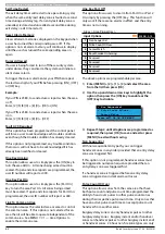
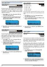
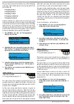
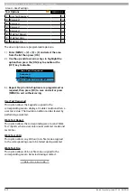
Page 67: ...armingthesystem allzoneswillbetestedbydefault and you may wish to turn this option off for certain zones so that you don t continually alert the operator during arming The sensor watch feature lets you monitor zones to ensure that they are working and detecting movement within a determined programmable period Zones by default can be bypassed and you should disable this option for zones you don t w...

Page 68: ... group The keypad will display the following zone array information for zones 1 to 16 0000000001111111 1234567890123456 NSA ANAT Press OK or MENU In the above example screen N Zone 01 and 06 are Normal Sealed S Zone 02 is Shorted A Zone 03 05 07 are in Alarm Unsealed T Zone 08 is in Tamper Alarm Unsealed Zone 04 09 16 are Disabled Unused 3 The keypad will display the following zone array informati...

Page 69: ... Press ON or OFF to toggle the zone bypass state then press OK to save and exit or press MENU to exit without saving 5 Repeat steps 1 to 4 to bypass or un bypass additional zones Inputs Commands Set Chime Zones MENU 3 0 3 This menu allows you to program zones to be monitored when chime mode is turned on Chime mode is ideal for monitoring a front door in a shop a pool gate or other entrance points ...

Page 70: ...set the smoke detectors in then press OK Smoke Detector reset in progress Please wait 2 The keypad will automatically return to the menu when all smoke detectors in the area has been reset i Note Smoke detectors must have the negative power terminal connected to an output programmed as Event Type 49 for this command to work ZONE DEFAULT TABLE The table below lists the default values for all zone p...

Page 71: ... No Exit Zones programmed as Instant 2 will immediatly cause the alarm to trigger when the zone is triggered ie No Entry Delay Zones set as Burglary Instant 2 have NO Exit Delay and are only active when the area is armed 05 Burglary Handover A Handover zone will provide a delayed alarm only when a delay zone has been tripped first ie the entry time is active otherwise it will trigger an instant al...

Page 72: ...t terminal to turn on and or off an area Refer to MENU 3 4 1 Keyswitch Options to select the various options such as latching or momentary arm and or disarm etc When reporting back to base the keyswitch user number will follow the actual zone number 14 Display Only A display zone is not a burglary zone It can never sound the sirens or trigger the dialler Its purpose is to only display on the keypa...

Page 73: ... refrigeration alarms as you may wish to only trigger an alarm condition if the fridge temperature sensor registers an out of temperature range for a time period before actually triggering the alarm i Note In previous versions a zone programmed with Option 14 PreDelay in MENU 3 1 3 would fail to register on the system if the zone was still faulted after the predelay time had expired In version 2 1...

Page 74: ...cess Group There are 8 different access groups Door Access Group Example 1 To set up a door access group you need to select an unused Access Group number from 1 to 8 in this example we will assume the Access Group number to be 5 2 Under user properties assign the users who you wish to have access to Access Group 5 Remember that you are able to assign users to more than one Access Group 3 Now selec...

Page 75: ...display the current Zone Report Route Report Route Zn1 01 Dest 1 Log Press 0 9 OK to SAVE 2 Use the up and down arrows to select the Report Route that you want to assign the zone to 3 Press OK to save and exit or press MENU to exit without saving i Note At factory default all Zones are set to report to Destination 1 and the System Log See the Zone Default Table for more information on Zone default...

Page 76: ...entered after the delay time has expired and the sirens are still sounding the system will send the Alarm report followed by a Cancel report Inputs Zone Properties Zone Options MENU 3 1 8 1 Lockout Siren Y 2 Silent Alarm N 3 Inverted Seal N 4 Bypass Allowed Y 5 Sensor Watch N 6 Armed In Part On Y 7 No EOL Required N 8 Test On Exit Y The above options are programmable per zone 1 Press MENU 3 1 8 an...

Page 77: ...gs An error beep will sound and a zone trouble message will display on the keypad advising the user to seal the zone s or to bypass them before the area will arm If this option is disabled the zone will not be tested during the arming sequence and the system will arm If the zone s are unsealled at the end of exit time a Zone Trouble report will be sent ADDING RF SENSORS The control panel supports ...

Page 78: ...w transmissions to establish a more accurate signal measurement GLOBAL INPUT OPTIONS Inputs Global Input Options EOL Value MENU 3 4 0 System Wide Parameter 0 5 00 No EOL 08 6k8 Ohm 01 1k0 Ohm 09 8k1 Ohm 02 1k5 Ohm 10 10k Ohm 03 2k2 Ohm 11 6K8 Alarm 2k2 Tamp 04 2k7 Ohm 12 10k Alarm 10k Tamp 05 3k3 Ohm 13 22k Ohm 06 4k7 Ohm 14 3k3 Alarm 6k8 Tamp 07 5k6 Ohm 15 Split EOL 3k3 6k8 This menu programs the...

Page 79: ... tamper alarm condition for the zone Response Time 500msec Setting this option will increase the response time for all zones to 500ms Keyswitch Open Close This feature allows you to select whether or not a zone programmed as a Keyswitch Zone will send opening and closing reports The default is set to Off Alarm On Tamper This option allows tamper circuits on RF sensors and hardwire zones to sound a...

Page 80: ...xpander Tpr Setting this option enables peripheral tamper reporting Audible Expander Tpr Setting this option causes the system to trigger an audible alarm when a peripheral tamper is triggered INPUT TESTING Inputs Input Testing Walk Test All Zones MENU 3 9 0 This menu allows you to test all zones within an area at the same time To perform a successfull walk test each zone in the area must be seale...

Page 81: ...ed for Sensor Watch are required to seal and unseal at least once within the Sensor Watch Time period or a trouble message will be displayed on the keypad and a Zone Trouble report sent Valid entries are 001 255 Days and 000 Sensor Watch Disabled 5 Press MENU 3 9 2 The keypad will display the current sensor watch time Default 30 days Sensor Watch Time 030 Days Press 0 9 OK to SAVE 2 Using the nume...

Page 82: ...Solution 6000 Installation Manual Input Programming 7 16 Bosch Security Systems 07 14 BLCC610I ...

Page 83: ...p of event type to event assignment Outputs 1 and 2 are special outputs that can be configured as horn speaker polarity types and are monitored to report a device connection trouble Output 4 is a dry relay contact which has a optional jumper that allows you to switch positive or negative without the need to add additional wiring The outputs are all protected and will shut down individually under o...

Page 84: ...RIGGERED On Condition F FAULT Overload Condition DISABLED 1 Enter MENU 4 0 2 and use the up and down arrows to select the output group to view 2 Use the up and down arrows at any time to move to a new group The keypad will display the following output array information for outputs 1 to 16 0000000001111111 1234567890123456 NNNNN TF Press OK or MENU In the above example screen N Outputs 01 to 05 are...

Page 85: ... access and secondly that you are a master code holder 1 Enter MENU 1 0 1 2 Use the arrow keys to highlight the door you wish to override then press OK Dr1 Door 1 Name Dr2 Door 2 Name Dr3 Door 3 Name Press OK or MENU 3 Use the ON and OFF keys to override the door and toggle the door open or close then press OK To abort press MENU Door 1 Name Dr1 Door Override is OFF To turn ON Press ON To Go Back ...

Page 86: ...type will cause the output to operate when the panel is communicating via Destination 1 Destination 2 or Destination 3 Email and will reset when the transmission ends 07 Reserved 08 Dest Kiss Off This event type will cause the output to operate when the panel receives an kiss off acknowledgment from the receiving party while communicating via destination 1 or 2 It is recommended that this output i...

Page 87: ...l only operate when all areas have been armed in All On or Part On mode The output will reset as soon any area is disarmed 23 Area All On This event type will cause the output to operate as soon as a specific area is armed All On mode and will reset when the area is disarmed If the event assignment for this output has been set to zero all areas then the output will only operate when all areas have...

Page 88: ...The output will reset when the area is armed or when a Part 2 On zone becomes unsealed If the event assignment for this output is set to zero all areas then the output will only operate if all areas are disarmed and all Part 2 On zones are sealed The output will reset if any area is armed or if any Part 2 On zone becomes unsealed 35 Close Sent OK This event type will cause the output to operate wh...

Page 89: ... Normally Low One Shot Open and program the output time parameter to be 5 seconds The smoke sensor needs to be connected to a zone input programmed as fire If fire alarm verification is required we recommend that you program the zone pulse count tor 2 pulses and the pulse count time to 90 seconds for each fire zone 50 Sensor Watch This event type will cause the output to operate when a zone sensor...

Page 90: ... their token The prox reader must be assigned to the same door group as the output and user The Event Assignment is the Access Group Number 61 Door Open Too Long This output will turn on when the control panel has detected that the zone assigned to the door has not returned to normal before the end of the door open too long time 70 User Panic The output will turn on when a user initiates a keyfob ...

Page 91: ...t without saving Outputs Properties Output Polarity MENU 4 1 3 0 0 00 Open To Low 08 Low To Open Pre 01 Open To Low Pre 09 Low Latching Open 02 Open Latching Low 10 Low Pulsing Open 03 Open Pulsing Low 11 Low 1 Shot Open 04 Open 1 Shot Low 12 1 Shot Open Retrigger 05 1 Shot Low Retrigger 13 1 Shot Open Reset 06 1 Shot Low Reset 14 Speaker Output 07 Low To Open 15 Toggle Theoutputpolarityprogramsho...

Page 92: ...ll pulse OPEN when the event occurs The output will reset when the output event restores Use the Time Parameter to set the pulse duration Low 1 Shot Open Output is normally LOW and will switch to open circuit when the event occurs The output will only reset when the time specified in the Time Parameter expires The output will run for the full duration and cannot be manually reset 1 Shot Open Retri...

Page 93: ...s MENU to exit without saving Off On Low Battery This option forces the control panel not to operate the output when a low battery or missing battery condition is in effect Once the low battery condition restores the output will return to normal operation Guest Control Guest control when enabled allows the output to be controlled from the quick select menu on the keypad which is a simple pull down...

Page 94: ...eZone MENU 4 2 2 0 0 00 Disabled 01 24 Hour TimeZone 09 TimeZone 9 Name 02 TimeZone 2 Name 10 TimeZone 10 Name 03 TimeZone 3 Name 11 TimeZone 11 Name 04 TimeZone 4 Name 12 TimeZone 12 Name 05 TimeZone 5 Name 13 TimeZone 13 Name 06 TimeZone 6 Name 14 TimeZone 14 Name 07 TimeZone 7 Name 15 TimeZone 15 Name 08 TimeZone 8 Name 16 TimeZone 16 Name The unlock timezone is used to control the output which...

Page 95: ... valid user has presented his card after the timezone unlocking gate opening time Report Door Forced This option when turned on will enable the Door Forced Open event to be reported as an access event It will also appear in the keypad display as an alarm condition identifying the door ALARM Door 1 Name Alarm Door Forced This otpion when turned on will enable the Door Forced Open event to cause an ...

Page 96: ...s to be manually stopped when testing is completed 1 Enter MENU 4 9 2 and select the area you want to test the strobe lights in from the list then press OK A1 Security System A2 Area 2 Name A3 Area 3 Name Press OK or MENU 2 Any outputs programmed for event type 48 in the chosen area will now operate The keypad will display the following during the strobe test Strobe Activated Will reset on exit Pr...

Page 97: ...7 Internal Audible A 71 CLI Trigger CLI 12 Output Device Missing P 38 Any Zone Alarm A 72 GSM Signal Lost P 13 Output Trouble Op 39 Fire Alarm A 73 GPRS Failure P 14 Panel On Line P 40 Burglary Alarm A 74 Ethernet Fail P 15 Incoming Call P 41 Silent Alarm A 75 Macro Ma 16 System Trouble P 42 Duress Alarm A 71 CLI Trigger CLI 17 Box Tamper Zn 43 Keypad Medical A 72 GSM Signal Lost P 18 Zone Trouble...

Page 98: ...ptional Output Relay Expander Boards CM710B are fitted Options marked N A Not Applicable Programming Option Output 1 Output 2 Output 3 Output 4 Output 5 Output 9 40 Output Name External Siren Strobe Light Smoke Sensor PWR Internal Siren On Board Relay Output x Name Event Type 36 External Siren 48 Strobe 49 Smoke Sensor GND 37 Internal Siren 54 Keyfob Function 2 00 Not Used Event Assignment 0 0 0 0...

Page 99: ...rmats called CID and SIA both formats are all predefined so the system will always send the same reporting code for the same event The type of zone selected under zone type automatically determines the reporting code to the base station If a zone is defined as Medical then when it goes into alarm the report will be Medical Alarm if a zone is programmed as a Fire zone then the report will automatic...

Page 100: ...e appropriate action This feature requires an optional voice module to be fitted to the control panel by your installer Additional programming information is included with the voice module When answering an incoming voice call the operations are as follows Acknowledge single message Acknowledge all messages hang up and leave in cue for next person Acknowledge message and leave in the cue for next ...

Page 101: ...m will then prompt you to Enter the message number followed by the OK key Enter the message number on the alarm keypad and press the OK key Zone 1 Message Zone 2 Message Zone 3 Message Press OK or MENU Alternatively you can use the UP and DOWN keys to scroll to the message required then press OK to select Refer to the voice module instruction sheet for a complete list of the message numbers 5 On t...

Page 102: ...s 3 Press OK to save and exit or press MENU to exit without saving Comms Telephone Numbers Destination 1 MENU 5 1 1 Phone 1 1 Digits 32 Phone 2 1 Digits 32 Phone 3 1 Digits 32 Phone 4 1 Digits 32 Phone 5 1 Digits 32 This menu sets the primary telephone number for Report Destination 1 This will typically be the primary base station receiver number The master code user can only change telephone numb...

Page 103: ...eft and right across the phone number Use the and keys to change the individual digit in the number or press the OFF key to clear the whole number and then enter the new number using the 0 9 keys 5 Press OK to save and exit or press MENU to cancel Comms Telephone Numbers Call Forward On MENU 5 1 6 1 Digits 32 6 1 2 0 The panel is able to activate certain Telco services such as Call Forwarding when...

Page 104: ...meric keys enter all digits for the sequence You can change a single digit by scrolling the cursor left or right For special characters including pause or use the up and down arrow keys 3 Press OK to save and exit or press MENU to exit without saving COMMS PROPERTIES Comms Properties Call Attempt Count MENU 5 2 0 0 6 This menu programs the maximum number of call attempts the panel will make per de...

Page 105: ...ort through as quickly as possible If this option is disabled the panel will wait for a period of 30 seconds before dialling the next telephone number in the sequence The 30 second timer starts when the first digit of the first telephone number is dialled Mirror Report WEB Reserved Extend H S To 1min This option sets the panel to wait for up to 60 seconds to receive a valid handshake signal from t...

Page 106: ...e at the panel when the dialler is on line is below 6 volts DC then you should set the Low Voltage option to yes i Note This option has been added in version 2 15 Display On Line This option allows the keypad to display Phone In Use when the telephone line has been looped by the control panel for either incoming or outgoing calls If this option is disabled no indication is provided on the keypad i...

Page 107: ...d to this number and Solution Link should be set to wait for an incomming call The installer or customer can force the panel to dial this number by entering MENU 5 0 1 For higher security the panel can be configured to always usethisnumberforcallbackverificationwhenestablishing a Solution Link remote access connection The following steps outline the callback procedure Step 1 Use Solution Link RAS ...

Page 108: ...ad will display the current threshold limit The default is 70 full Log Threshold 070 Percents Press 0 9 OK to SAVE 2 Using the numeric keys enter the new threshold limit then press OK to save and exit or press MENU to exit without saving There is no need to enter the symbol i Note Each time a Solution Link RAS session is established with the panel the log information will be uploaded to the Soluti...

Page 109: ... the control panel to only allow remote telephone line RAS sessions when all areas are turned off disarmed If this option is not set the control panel will allow remote telephone RAS sessions when any and or all areas are turned All On or Part On and Off Allow User Functions Setting this option allows access to user functions via the RAS upload download software If this option is not programmed us...

Page 110: ...AMPLES Each example below shows the log on step for clarity In practise is only necessary to log on once per DTMF control session To turn Area 1 ON enter the following 2 5 8 0 Log ON 1 1 1 Arm Area 1 To turn Output 10 ON enter the following 2 5 8 0 Log ON 2 1 0 1 Turn Output 10 ON To turn Output 12 OFF enter the following 2 5 8 0 Log ON 2 1 2 2 Turn Output 12 OFF i Note If the DTMF Quick Arm optio...

Page 111: ...at you wish to program 4 Press OK to save and return to the MENU i Note Up to 3 Phone numbers can be entered for CLI Call Line Identification for remote access detection You must enter STD code plus the compete number for this option to work Press OK after each telephone number is entered to save and move to the next number i Note The control panel is only required to match part of the CLI telepho...

Page 112: ...down arrow keys to select the Transmission Format required then Press OK to save and exit or press MENU to exit without saving i Note A feature for GSM SMS reporting has been included to allow the control panel to first call the telephone numberthattheSMSeventwillbesentto Thisfeature is very helpfull when an alarm event occurs while you are sleeping as the longer alert tone will wake you where as ...

Page 113: ...ents Only 0 1 01 Dest 1 Log 02 Dest 2 Log 03 Dest 1 2 Log 04 Dest 2 If 1 Fails System Wide Parameter This menu programs the destination that all Keypad emergency alarms are reported 1 Press MENU 5 4 4 The keypad will display the current Emergency Route Emergency Route 01 Dest 1 Log Press 0 9 OK to SAVE 2 Use the up and down arrow keys to select the Keypad Emergency route required then Press OK to ...

Page 114: ...K to SAVE 2 Using the numeric keys enter the new report delay time then press OK to save and exit or press MENU to exit without saving Valid entires are 0 to 255 seconds MYALARM Comms MyAlarm IP Address MENU 5 5 0 1 Digits 12 0 0 0 0 0 0 0 0 0 0 0 0 This menu programs the 12 digit MyAlarm IP Address i Note MENU 5 5 0 should be left at the factory default settings unless you are advised otherwise b...

Page 115: ...current gateway telephone number Gateway Numbers SMS Pri 183213450641 Press 0 9 OK to SAVE 3 Using the numeric keys enter all the digits of the gateway telephone number You can change a single digit by scrolling the cursor left or right For special characters including pause or use the up and down arrow keys 4 Press OK to save and exit or press MENU to exit without saving Comms MyAlarm Email Addre...

Page 116: ...Zones This option allows the control panel to report zone alarm and trouble reports via email System This option allows the control panel to report via email numerous system reports e g AC Fail Low Battery etc via email Access This option allows the control panel to report via email when a valid token has been swiped eg Access Granted or Access Denied Comms IP Reporting Receiver IP MENU 5 6 0 Dest...

Page 117: ...ess then press OK to save and exit or press MENU to exit without saving Comms IP Reporting Poll Rate MENU 5 6 2 0 3 6 0 Seconds x 10 This menu allows the installer to program how often the control panel sends a signal to the base station receiver via Destination 1 and or Destination 2 The poll interval programmed in seconds and then multiplied by 10 eg 0009 90 sec s 0360 1 hr 4320 12 hrs and 8640 ...

Page 118: ... destination 1 or 2 that you want to program the acknowledge wait time Rr1 Dest 1 Rr2 Dest 2 Exit Press OK or MENU 2 Highlight the destination number 1 or 2 required then press OK to select 3 The keypad will display the current IP format IP Format Rr1 01 Conettix NNC Press 0 9 OK to SAVE 4 Use the numeric keys 0 to 9 to program the new IP format required then press OK to save and exit or press MEN...

Page 119: ...x Dest Nº 2 1 Digits 6 0 0 0 0 0 0 Receiver Prefix Dest Nº 1 1 Digits 6 0 0 0 0 0 0 Receiver Prefix Dest Nº 2 1 Digits 6 0 0 0 0 0 0 Account Number The account number is the most specific token and is always programmed into the premises equipment to identify it The account token appears both in the header of the message which is never encrypted and in the data of the message which may be encrypted...

Page 120: ...to program then press OK to select Username Rr1 Press OK to SAVE 4 Use the 0 to 9 and and keys to program the parameter then press OK to save and exit or press MENU to exit without saving Comms IP Remote Access IP Address MENU 5 7 0 Installer 1 Digits 12 0 0 0 0 0 0 0 0 0 0 0 0 User 1 Digits 12 0 0 0 0 0 0 0 0 0 0 0 0 This menu allows the installer or master user the ability to program the Solutio...

Page 121: ... 1 IP RAS Allowed Y 2 RAS Only If Disarmed N 3 Report IP Session Y 4 Report IP Lockout Y 5 UDP Installer RAS Y 6 UDP User RAS N 7 Reserved N 8 Reserved N This menu allows the installer to select which IP options are allowed 1 Press MENU 5 7 2 The keypad will display the current options which are selected or enabled IP RAS Allowed RAS Only If Disarmed Report Session Press OK ON OFF MENU 2 Use the n...

Page 122: ... 12 2 0 2 1 2 9 0 8 3 0 5 8 This menu is reserved for factory use Do not change unless requested to do so 1 Press MENU 5 7 5 The keypad will display the current IPRS address DNS Address 202129083058 Press OK to SAVE 2 Use the numeric keys 0 to 9 and keys to program the 12 digit IPRS address then press OK to save and exit or press MENU to exit without saving Comms IP Remote Access IPRS Port MENU 5 ...

Page 123: ...elect the Test Report Period then Press OK to save and exit or press MENU to exit without saving Comms Comms Test Test Report Options MENU 5 9 3 1 Test If No Other Rpt N 2 Test On Siren Reset Y 3 Reserved N 4 Reserved N 5 Reserved N 6 Reserved N 7 Reserved N 8 Reserved N 1 Press MENU 5 9 3 The keypad will display the current Test Report Options Test If No Other Rpt Test On Siren Reset Reserved Pre...

Page 124: ...theneedtotriggertestreportsandthen verify them with the base station Once the telco wiring has been completed enter your mobile phone or another test number into this location and press OK The panel will then seize the phone line and dial the programmed number 1 Press MENU 5 9 5 then select either PSTN or GMS communication to test the dialler if an optional GSM module has been fitted GSM PSTN Exit...

Page 125: ...croll the keypad voltage temperature and area while the device type and firmware version number are continuously displayed Keypad 1 Name Kp1 Graphic Prox V2 05 Voltage 13 87 Press OK or MENU 3 Press OK or MENU to exit when finished i Note In previous versions when selecting to view the status of the ethernet module the status line did not include the MAC address or IP address of the CM751B etherne...

Page 126: ... 3 and use the up and down arrows to highlight the device in the list 001 Fp2 Keypad 1 Name 017 Kp1 Keypad 3 Name 010 Kp1 Keypad 5 Name Press OK or MENU 2 Press OK or MENU to exit Devices Commands Keypad Volume MENU 6 0 7 This menu allows you to adjust the volume of the keypad s speaker to suit the application or customer preference Each keypad on the system can be adjusted separately 1 Press MENU...

Page 127: ...ming Allowed Part On Arming Allowed Disarming Allowed Press OK ON OFF MENU 3 Repeat Step 2 until all options are programmed as required then press OK to save and exit or press MENU to exit without saving All On Arming Allowed Selecting this option allow the user to turn the area All On that the keypad or LAN reader is assigned to when a valid PIN token or fingerprint is presented The user must hav...

Page 128: ...reas Present Finger and Hold Opens Door Turns Part On All User Areas Table 26 Fingerprint Non Badging Examples Badging Allowed Area Is All On Present Finger Once Open Door Turns Off All User Areas Area Is Part On Present Finger Once Open Door Turns Off All User Areas Area Is Off Present Finger Once Open Door Present Finger and Hold Opens Door Turns On All User Areas Table 27 Fingerprint Non Badgin...

Page 129: ...il all options are programmed as required then press OK to save and exit or press MENU to exit without saving Enable Rear Tamper This option allows the tamper circuit located on the back of the LAN device to function As soon as the LAN device has been removed from the wall the control panel will register an alarm event For this option to work the keypad model being used must have the on board tamp...

Page 130: ... Where the console is then assigned to a door triggering this input will then trigger the door to operate for the programmed time thus allowing access Log Egress Events There can be many Egress events per day on an access control system which can clutter the history log over time If you enable the Log Egress Events option then the egress events are recorded into the history log for later review De...

Page 131: ...t warning tone when a user turns an area All On Part Exit Warning This option allows the LAN device keypad proximity reader or fingerprint reader to sound the exit warning tone when a user turns the area Part On or Part 2 On If this option is not programmed the keypad will only sound a single beep at the end of the part exit time Chime Tone This option allows the LAN device keypad proximity reader...

Page 132: ...ons theholddownemergencyalarm functions using the arrow keys failed to operate when initiated using graphic keypads that have built in smart card readers This included keypad fire keypad panic and keypad medical emergency alarms In version 2 14 the hold down emergency functions using the arrow keys now function correctly Devices Keypads Readers Door Assignment MENU 6 1 7 0 0 00 No Door Assignment ...

Page 133: ... restore report will be sent when the tamper circuit is resealled Alarm RF Rcvr Jamming Setting this option allows the panel to sound an alarm when the RF Receiver detects a jamming signal This signal may not be provided by all compatible RF Receivers Report RF Rcvr Jamming Setting this option allows the panel to send an RF Receiver Jam report to the base station when the RF Receiver detects a jam...

Page 134: ...s a low battery condition Report Lost RF Devices Setting this option will cause the panel to send a report to the base station if the panel detects that an RF device is missing Open Zone On Lost RF Setting this option will cause the panel to show a zone fault on the keypad for any RF devices that are missing Audible Keyfob Panic Setting this option allows users who have RF keyfobs to trigger an au...

Page 135: ...dshake 0 0 01 Hardware 02 Xon Xoff This menu sets the appropriate flow control for the device you are connecting the serial board to The flow control method must be the same on both devices for a serial connection to be established 1 Press MENU 6 3 2 The keypad will display the current flow control setting Flow Control 00 No Handshake Press 0 9 OK to SAVE 2 Use the up and down arrow keys to select...

Page 136: ...p and down arrow keys to highlight the option then press the ON key to enable or the OFF key to disable 3 Repeat Step 2 until all options are programmed as required then press OK to save and exit or press MENU to exit without saving Auto Forward SMS Any SMS received by the GSM module will be automatically forwarded to the mobile telephone number programmed in MENU 6 5 7 Forward SMS To Mail Any SMS...

Page 137: ...s 16 Phone 10 1 Digits 16 GSM MODULE REQUIRED The CLI trigger table allows you to program up to 10 telphone numbers that the control panel will automatically identify when you call the control panel to operate an output see Output Event type 71 Program the output event assignment as 2 so that the output follows CLI trigger table 2 1 Enter MENU 6 5 5 1 The keypad will display the following Phone 1 ...

Page 138: ...onfirm Turn Multiple Outputs On User Code Output 1 2 3 4 ON Turn Multiple Outputs On With Confirmation User Code Output 1 2 3 4 ON Confirm Turning Output 1 OFF User Code Output 1 OFF Turning Output 1 OFF With Confirmation User Code Output 1 OFF Confirm Turning Multiple Outputs OFF User Code Output 1 2 3 4 OFF Turning Multiple Outputs OFF With Confirmation User Code Output 1 2 3 4 OFF Confirm Check...

Page 139: ...mber that you wish to program 4 Press OK to save and return to the restrict SMS control table otherwise press MENU to exit without saving Devices Ethernet Module Module IP Address MENU 6 6 0 1 Digits 12 0 0 0 0 0 0 0 0 0 0 0 0 This is the IP address of the TCP IP module on the customer s internal local area network 1 Press MENU 6 6 0 The keypad will display the current IP address Module IP Address...

Page 140: ... Report Poll Fail Y 5 Reserved N 6 Reserved N 7 Reserved N 8 Reserved N This menu option allows you to configure the various RF receiver functions Only one RF reciever can be fitted per panel 1 Enter your Installer PIN MENU 2 Enter 6 6 9 OK The keypad will display the current options which are selected or enabled Display Faults Report Cable Lost Report IP Conflict Press OK ON OFF MENU 3 Use the nu...

Page 141: ... OK to exit when finished System Commands System Trouble MENU 7 0 1 This command lists any system troubles which are currently in effect on the system Information is diplayed in a list format allowing you to select a paticular event and then drill down to view more specific information System trouble events such as Failure To Comminicate or Telco Line Fail are grouped under System Trouble in the l...

Page 142: ... Missing This trouble message will display if the panel detects the RF receiver is missing or disconnected The trouble will clear when the receiver is reconnected Case Tamper This trouble message will display if the panel detects that the tamper circuit on the RF receiver is faulted Receiver Jam This trouble message will display if the connected RF receiver detects RF noise levels that may prevent...

Page 143: ...nge like a user name then exit programming mode If this problem still persists you must do a full system default Phone Line In Use This trouble message will display while the panel is using the phone line The message will clear when the line is released This message can be prevented from displaying in MENU 5 2 2 Phone Line Options Battery Trouble The control panel has detected that the real time c...

Page 144: ...refore only emergency burglary and fire reports will be sent The following table list the changes that will occur when you select domestic default using MENU 7 0 3 Program Option Domestic Default Value All Trouble Reports Disabled All Bypass Reports Disabled All Restore Reports Disabled Destination 1 TX Format Domestic Reporting Access Route Log Only Open Close Reports Log Only Test Route Log Only...

Page 145: ... 0 6 and use the up and down arrows to select the timezone to view The keypad will display the status of all 16 timezones 0000000001111111 1234567890123456 TTTTT FFFF Press OK or MENU In the example above T TimeZones 01 to 05 are true F TimeZones 09 to 12 are false TimeZones 06 to 08 and Doors 13 to 16 are Disabled or Not Available 2 When finished press OK or MENU to exit System Commands Service M...

Page 146: ... the left and right keys to move the cursor between the month week and year 3 When finished press OK to save and exit or press MENU to exit without saving System Clock Summertime Off MENU 7 1 2 At 2 00am Month Week Day This menu allows you to program when day light savings end during the year This will allow the panel to automatically adjust it s built in clock accordingly In Australia daylight sa...

Page 147: ...wer supply has failed If the power remains missing continiously for 1 minute then a system trouble will be registered on the keypad When the AC power supply returns to normal the Mains Power icon will remain on steady If this option is disabled then the system will not flash the Mains Power icon and no system trouble will occur Report AC Fail Setting this option will cause the panel to report an A...

Page 148: ... voltage below 10 2 volts then a Battery Test Failed report will be sent A Battery Test restore will be sent when the battery is re connected or replaced Battery Test On Arming Setting this option will cause the panel to perform an additional dynamic battery test each time Area 1 is armed All On OK To Arm Low Battery Setting this option will allow the system to be armed even though the panel curre...

Page 149: ...at Steps 2 and 3 until the desired siren tone is achieved then press OK to save and exit or press MENU to exit without saving i Note Only outputs programmed as Event Type 36 and or 37 will be affected by this menu option System Siren Speed MENU 7 4 1 This menu allows you to customise the speed of the siren tone when a non fire alarm is triggered By changing the tone and speed it is possible to pro...

Page 150: ...es TRUE whenever the time is equal to or after the start time and before the end time for the selected day There are 2 default timezones created within the system that cannot be changed These are Tz0 Disabled which is FALSE 24 7 and Tz1 24 Hour which is TRUE 24 7 TZ1 being the opposite of Tz0 Tz2 to 16 are configurable to reflect any operation time and day as required to operate restrict or contro...

Page 151: ... you to program the start time and stop time of each timezone period Each timezone can have up to 4 different periods 1 Enter MENU 7 5 1 and use the up and down arrows to highlight the time zone in the list then press OK Alternatively you can enter the time zone number directly and press OK Tz2 TimeZone 2 Name Tz3 TimeZone 3 Name Tz4 TimeZone 4 Name Press OK or MENU 2 Using the arrow keys select t...

Page 152: ... period required then press OK to select Each timezone include 4 seperate start stop periods that can be programmed Period 1 Period 2 Period 3 Press OK or MENU 3 Use the up and down arrow keys to highlight the option then press the ON key to enable or the OFF key to disable Repeat Step 2 until all options are programmed as required Invert Period Logic Master Edit Allowed Reserved Press OK ON OFF M...

Page 153: ...rence between start and stop dates SYSTEM OPTIONS System System Options General Options MENU 7 7 0 1 Display LAN Fail Y 2 Report LAN Fail Y 3 Alarm On LAN Fail N 4 Cannot Change Own PIN N 5 Reserved N 6 Monitor Default PINs Y 7 PIN Always Required N 8 Display Menu Numbers Y System Wide Parameter This menu allows you to configure the General system options All options are global to users areas and ...

Page 154: ...n armed or turned All On Reset Siren All Users Setting this option allows a user with a valid PIN to silence alarm outputs from any keypad on the system without the need to toggle the keypad to the area that the alarm occurred If this option has not been programmed the user will need to toggle the keypad to the area the alarm occurred in and then silence the alarm by entering their PIN followed by...

Page 155: ...Press MENU 7 7 3 The keypad will display the current temperature settings Keypad Hi Lo Temp High Temp Low Temp 000 000 Press OK to SAVE 2 Use the up and down arrow keys to program the High and Low temperatures Use the left and right arrow keys to move between the High and Low temperatures Valid range 000 C to 050 C 3 Press OK to save and exit or press MENU to exit without saving System System Opti...

Page 156: ...er PIN is not know then the panel will need to be returned to Bosch Security for defaulting A charge applies for this service i Note Defaulting the panel does not erase all events in the history event log If this option has been disabled the dialler seize relay will pulse or click 4 times during power up System System Options Language MENU 7 7 5 0 English 0 1 Alternate Language This menu allows yo...

Page 157: ...lly tested will no longer scroll on the keypad display When all zones have been tested the keypad will display All zones have been successfully tested Press OK or MENU 4 Press OK to save and exit or press MENU to exit without saving System System Testing Battery Test MENU 7 9 1 This menu allows you to test the panels standby battery The battery test will last about two minutes and the keypad will ...

Page 158: ...Solution 6000 Installation Manual System Programming 11 18 Bosch Security Systems 07 14 BLCC610I This page left intentionally blank ...

Page 159: ...h time button 5 OK is pressed on the keypad the door will activate Opening a Garage Door Using a 4 Button RF Keyfob The following example show how to configure the control panel to allow control of a grage door as well as arm and disarm functions using a 4 Button Keyfob The example assumes User 10 and Output 5 are being used Procedure 1 Set RF Receiver Type in MENU 3 5 0 04 Bosch Serial Rcvr 2 Ass...

Page 160: ...o access the door Unlocking a Door and Disarming Area 1 using a LAN Reader This example assumes LAN Reader 9 Door Assignment 4 User 1 and Output 5 are being used Procedure 1 Assign LAN Reader 9 to Door Assignment 4 in MENU 6 1 7 2 Set output 5 to Event type to 60 Door in MENU 4 1 1 and the output Door Assignment to 4 in MENU 4 1 2 Set the output Polarity in MENU 4 1 3 and the output Time Parameter...

Page 161: ...nfigured to report via SMS using an optional GSM module if one is fitted The procedure for implemeting SMS via GSM is different to the procedure shown above Please consult the GSM module instructions for more information Door Auto Lock Unlock By TimeZone The control panel is capable of automatically unlocking and locking single door or multiple doors using a single timezone Programming the TimeZon...

Page 162: ...Solution 6000 Installation Manual Programming Examples 12 4 Bosch Security Systems 07 14 BLCC610I E N D O F S E C T I O N ...

Page 163: ...2 2006 EN 60950 1 2001 Amdt 11 2004 AS NZS 60950 1 2003 Amdt 1 2006 AS ACIF S002 2005 PTC200 May 2006 ETSI TS 103 021 1 2 3 Compatible Keypads CP050B Night Arm Station CP150B External Vandal Resistant Keypad CP151B External Vandal Resistant Keypad CP700B Graphic White CP701B Graphic Prox White CP710B Graphic Black CP711B Graphic Prox Black CP740B Graphic Keypad With WiFi White CP743B Graphic Keypa...

Page 164: ...e Administration Software CM900 Direct Link Cable CM901 Flash Upgrade Cable CM255 Default Key The following parts are supplied with the panel Australian models only content may differ in export models Panel Assembly Includes 1 x Metal Enclosure with tamper 1 x Panel PWA 1 x User Manual 1 x Installer Reference Guide 1 x Resistor Pack Resistor Pack Includes 1 x Red Battery Lead 1 x Black Battery Lea...

Page 165: ...CP050B Night Arming Station Graphic Keypad P N CP700B White F 01U 275 889 P N CP710B Black F 01U 275 891 Graphic Keypad With WiFi P N CP740B White F 01U 294 858 P N CP743B Black F 01U 294 860 Graphic Keypad with Built In Prox Reader P N CP701B White F 01U 275 890 P N CP711B Black F 01U 275 892 Graphic Keypad with Internal Smart Card Reader P N CP722B White F 01U 294 854 P N CP732B Black F 01U 294 ...

Page 166: ...N CM797B LAN Isolator Module F 01U 275 885 Up to 8 zone expanders of any type can be connected to the system When using Single or Alarm Tamper EOL the CM707B can be installed to provide 16 zones on the CM705B Expander The CM707B cannot be installed when using split EOL monitoring Max panel zone count configuration is Single EOL 136 Alarm Tamper 136 Split EOL 144 P N CM705PB 8 16 Universal LAN Zone...

Page 167: ...rt 6 10 Auto Exit Installer Menu In 2 Min 11 15 Auto Exit Service Mode In 2 Hrs 11 16 Automatic Arming 4 10 B Basic Operations Automatic Arming 4 10 Duress Alarm 4 11 Remote Arming Quick Arm 4 11 Turning An Area All On 4 10 Turning An Area Off 4 10 Turning An Area Part On Part 2 On 4 10 BASIC REPORTING REFERENCE 4 5 Battery Options Display Fail 11 8 Execute Test On Arm 11 8 OK To Arm Low Battery 1...

Page 168: ...ult 11 4 Allowed 11 16 Fault Acknowledge All Areas 11 14 Fault ACK Required 6 4 Features 1 1 Fingerprint Add 5 12 Delete 5 12 Status 5 12 Fire Alarm 6 6 Fire Report Delay 9 16 First To Open Last To Close 11 14 Fuse Options Display 12V Overload 11 8 Display COMM Overload 11 8 Display LAN Overload 11 9 Report 12V Overload 11 9 Report COMM Overload 11 8 Report LAN Overload 11 9 G GSM GPRS Module Opti...

Page 169: ...wed 10 3 PIN To Change Area 10 4 Reader Area Control 10 5 Reader Badging 10 5 Rear Tamper 10 5 Report Temperature 10 5 Show Alarm When Armed 10 5 Single Key Control 10 3 Temperature Display 10 7 Zero Exit Time 10 3 Keyswitch Input On Off Flash Strobe 6 6 Keyswitch Options 7 12 Keyswitch Tamper Alarm 6 5 L Language 11 16 LAN Scan 10 2 LAN Secure 10 1 Link To Common Area 6 4 Locale 11 7 Lockout Dial...

Page 170: ... Delete RF Device 7 12 RF Device Options 10 10 RF Receiver Options 10 9 Supervision Time 10 9 Test RF Device 7 12 View RF ID 10 10 RF Receiver Options 10 9 Ring Count 9 10 S Senior Watch 6 5 Senior Watch Time 6 10 Sensor Watch 7 11 Sensor Watch Time 7 15 Service Interval 6 11 SERVICE MODE 11 5 Silencing Alarms 4 10 Silent Alarm 7 10 Silent Burglary Alarm 6 6 Single Key Arming 6 4 Off From Part On ...

Page 171: ... User Test Required 6 12 View PIN 5 4 V View PIN 5 4 View RF Device ID 10 10 Voice Access Code 9 12 Voice Module Setup 9 2 W Walk Test All Zones 7 14 11 17 Walk Test A Zone 7 14 Walk Test Options User Test Required 6 12 Walk Test 24Hr Zones 6 12 Walk Test Fire Zones 6 12 Walk Test Reports 6 12 WIRING Board Connectors 3 2 PCB Overlay 3 6 Terminal Descriptions 3 2 Zone Wiring 3 1 Z Bypass Zones 7 2 ...

Page 172: ...Bosch Security Systems 25 Huntingwood Drive Huntingwood NSW 2128 Australia Phone 612 9672 1777 Facsimile 612 9672 1717 2014 Bosch Security Systems BLCC610I Issue FTR1 1 ...

Reviews: