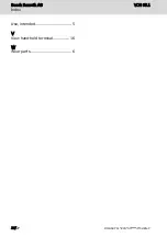
Index
A
Accessories..................................... 6
Accumulators................................ 22
Ambient conditions......................... 6
Assembly....................................... 13
B
Batteries....................................... 22
C
Cable installation.......................... 13
CE marking................................... 11
Complaints..................................... 2
Connecting to the connection
module VAC.................................. 15
Connection to the control............ 16
Criticism......................................... 2
Customer Feedback........................ 2
D
Declaration of conformity............. 11
Device description........................ 16
Disassembly.................................. 13
Disposal........................................ 21
Documents, further......................... 2
E
Electrical connection.................... 13
Electrical safety and fire protection
Standards................................ 10
EMC Directive
Examination of conformity...... 10
Error causes.................................. 18
Error elimination........................... 18
F
Feedback........................................ 2
Further documents......................... 2
H
Housing dimensions...................... 13
I
Intended use................................... 5
Interfaces...................................... 12
M
Maintenance................................. 18
O
Operating system.......................... 17
Order information........................... 6
Ordering information.................... 20
P
Product identification..................... 2
S
Safety alert symbol......................... 4
Safety instructions...................... 3, 4
Scope of delivery............................ 3
Selecting the connection
modules........................................ 16
Settings........................................ 15
Signal words................................... 4
Software-specific settings............ 15
Spare parts..................................... 6
Standards....................................... 9
EMERGENCY STOP push-
button.................................. 9, 10
Suggestions.................................... 2
Support
See service hotline.................. 22
Symbols.......................................... 5
T
Target groups................................. 1
Technical data................................ 7
EMERGENCY STOP pushbutton 8
Enabling button......................... 8
Hand-held terminal.................... 7
Keyboard, housing, display........ 7
Stop button............................... 8
Type code..................................... 21
Type plate....................................... 3
U
UL/CSA certified........................... 11
Updating the operating system..... 19
VCH 05.1
Bosch Rexroth AG
Index
DOK-SUPPL*-VCH*05*****-IT02-EN-P
25/27

