Modifications in the cable chamber:
●
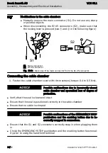
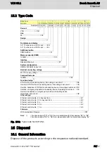
Manually remove the main connector (S1). Do not use any sharp
or pointed objects
●
When disconnecting the RJ-45 connectors (S2), make sure that
the locking lever is pressed (see
①
and
②
in the following figure)
1
2
S1
S2
S1 Main connector
S2 RJ-45 connector
Fig. 10-2: Disconnect the main connector from the RJ-45 connector
Connecting the cable chamber
1. Fasten the cable chamber cover with three screws (torque: 0.4 to 0.5 Nm).
Possible malfunctions due to incorrectly closed
cable chamber and sporadical loss of degree of
protection.
NOTICE
●
Verify that the seal is clean and intact
●
Ensure that the seal is positioned correctly in the cable chamber
●
Ensure that no cable is crimped
Possible malfunctions of the EMERGENCY STOP
pushbutton and the enabling button due to in-
correctly snapped in connectors.
NOTICE
●
Ensure that the S1 and S2 connectors correctly snap in when plugging them
in
●
Check the EMERGENCY STOP pushbutton and the enabling button functional-
ity prior to using the hand-held terminal
Bosch Rexroth AG
Assembly, Disassembly and Electrical Installation
VCH 05.1
14/27
DOK-SUPPL*-VCH*05*****-IT02-EN-P

