background image

10/20 

Bosch Rexroth AG 

Assembly Instructions for Hydraulic Power Units |  RE 07009-MON/11.17

5.1.3  Use of attachment points

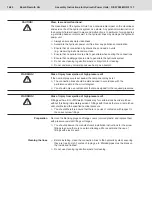
Danger to life due to tumbling, falling or uncontrolled movement of the 

hydraulic power unit when using unsuitable attachment points!

After a longer period of use, the attachment points may no longer be in place, be 

sufficiently stable or identifiable as such.


f

Refer to the product-specific documentation for the intended attachment 

points and only use the ones mentioned there.


f

Check the stability of the attachment points if you intend transporting the 

hydraulic power unit after dismantling.


f

Replace missing and/or defective attachment points, if possible. This work 

should be carried out in a professional manner.


f

Insert the screw-in attachment points into the tapped hole and hand-

tighten fully.


f

If necessary, mark the unrecognizable attachment points using easily 

visible color.

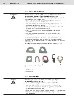
Attachment points are fixtures in the form of lugs, collars or shackles that 

are connected to the hydraulic power unit by means of welded or threaded 

attachment. They are designed for lifting or holding down the hydraulic power unit 

during transport.
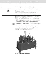
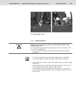
Examples of attachment points of hydraulic power units are shown in Fig. 3:


1


2

Fig. 3: Examples of attachment points

Welded type 

Screwed type

5.1.4  Manual transport

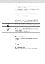
Risk of injury to persons undertaking manual lifting/handling due to 

overloading and incorrect posture!

In the case of lifting/handling, there is the risk of damage to health due to 

overloading and incorrect posture. 


f

The limits of the respective persons involved in manual lifting/handling 

must be realistically assessed. Muscular strength and constitution differs 

considerably among human beings.


f

Wherever possible, suitable lifting aids should be used such as e.g. carrying straps.


f

Always use appropriate techniques when lifting, setting down and 

moving products.

WARNING!

CAUTION!

Summary of Contents for Rexroth RE 07009-MON

Page 1: ...RE 07009 MON 11 17 Replaces 09 09 English General Assembly Instructions with Information on the Transport of the Hydraulic Power Units Assembly instructions ...

Page 2: ...verification It must be remembered that our products are subject to a natural process of wear and aging ⓒ This document as well as the data specifications and other information set forth in it are the exclusive property of Bosch Rexroth AG It may not be reproduced or given to third parties without its consent The cover shows a sample configuration The product supplied may therefore differ from the...

Page 3: ...wing instructions 6 3 Scope of delivery 7 4 Product description 7 4 1 Product identification 7 5 Transport and storage 8 5 1 Transporting hydraulic power units 8 5 2 Storing the hydraulic power units 14 6 Assembly and installation 14 6 1 Unpacking 14 6 2 Assembling the hydraulic power unit 15 6 3 Installing the hydraulic system 15 6 4 Connecting to the water supply 17 6 5 Installing the electrical...

Page 4: ...4 20 Bosch Rexroth AG Assembly Instructions for Hydraulic Power Units RE 07009 MON 11 17 Contents ...

Page 5: ...ly f f Always include the operating instructions and the product specific documentation when passing the hydraulic power unit hydraulic assembly on to a third party 2 1 Intended use For information on the intended use please refer to the supplied general operating instructions for hydraulic power units and hydraulic assemblies 2 2 Qualification of personnel Assembly requires a basic knowledge of m...

Page 6: ...oderate injury or damage to equipment If this information is disregarded it may result in machine malfunction or breakdown Warning signs Meaning Warning of a danger spot 2 4 Adhere to the following instructions The regulations regarding accident prevention and environmental protection applicable in the country where the product is used and at the workplace must be observed Only persons who have be...

Page 7: ...ower units also includes both general and product specific documentation These documents are listed in the following table Document Power unit Product specific documentation Technical specification x Hydraulic diagram x Component list to hydraulic diagram x Assembly drawing x EC Declaration of Incorporation x General documentation Operating Instructions x Assembly instructions this document x 4 Pr...

Page 8: ...e foundation on suitable ground f f By means of additional suitable measures e g by securing holding down points or with the use of cranes provide for sufficient stability before removing any packing transit materials or fixtures f f Only the intended locations and attachment points should be used for securing or lifting the hydraulic power unit f f Hydraulic power units must never be attached to ...

Page 9: ...epressurize the installed accumulators on the oil side If possible reduce the pressure on the gas side to a value of 2 bar 200 kPa Bosch Rexroth always delivers hydraulic power units without first filling with oil Any deviations from this rule are described explicitly in the product specific documentation From the factory inspection there may however still be oil residues in the product 5 1 2 Dete...

Page 10: ...nrecognizable attachment points using easily visible color Attachment points are fixtures in the form of lugs collars or shackles that are connected to the hydraulic power unit by means of welded or threaded attachment They are designed for lifting or holding down the hydraulic power unit during transport Examples of attachment points of hydraulic power units are shown in Fig 3 1 2 Fig 3 Examples ...

Page 11: ...fications including safety training for the respective device You should proceed as follows f f Using suitable temporary protective devices e g wooden or plastic elements protect the hydraulic power unit against the contact surface of the fork so that the paintwork cannot be damaged during lifting and transport f f Secure the hydraulic power unit at the forklift against tilting To this purpose fus...

Page 12: ... attachment device e g lifting straps harnesses or chains should be used f f Use only the intended locations and attachment points when lifting see Fig 5 and 6 f f Ensure that the built on components of the hydraulic power unit do not come into contact with the attachment device or lifting tools during transport The edges of the hydraulic power unit may cause damage to the fabric lifting straps or...

Page 13: ... any resulting acceleration forces as required The various regulations of the assigned forwarding agents e g shipping companies railway companies forwarders airlines must be observed f f Secure the hydraulic power unit onto the transport vehicle e g by the holding down points f f Ensure that the built on components of the hydraulic power unit do not come into contact with the attachment devices du...

Page 14: ...ding its overall function and logic mode of operation please refer to the instructions and or the documentation for the complete machine Risk of personal injury and damage to property A basic knowledge of hydraulics is required for assembling the hydraulic power unit f f Only qualified personnel see Chapter 2 3 Personnel qualifications are permitted to assemble the hydraulic power unit 6 1 Unpacki...

Page 15: ...ociated with mounting is consistent f f Level the hydraulic power unit so that its longitudinal and transverse axes are horizontal f f Prevent possible bouncing by suitable means e g height adjustment of the feet insertion of shims packers f f Securely fix the product at the mounting positions specified in the product specific documentation 6 3 Installing the hydraulic system Risk of injury when a...

Page 16: ...f the nominal pressure is exceeded the component may burst f f The connection lines should be dimensioned in accordance with the performance data in the circuit diagram f f You should only use components that are designed for the required pressures Risk of injury from ejection of high pressure oil Fittings with metric or Whitworth threads may for certain sizes be mis matched without this being imm...

Page 17: ... voltage If you fail to switch off the power supply before assembling the product you may suffer injury destroy the product or damage system components f f Always switch off the power supply to the relevant system component before assembling the product 6 5 1 Earthing and potential equalization Hydraulic power units from Bosch Rexroth are supplied with connection for the external earthing system P...

Page 18: ...control and monitoring equipment Connect the control and monitoring equipment switching devices open loop or closed loop equipment or frequency converters according to the relevant instructions taking into account the appropriate safety precautions Penetrating dirt and liquids will cause faults Safe function of the hydraulic power unit components is then no longer ensured f f Always ensure absolut...

Page 19: ... belts or chains Component Any part with a partial function in the sense of the technical overall system Components in the hydraulic system include e g valves filters cylinders hydraulic connection elements Floor conveyors Floor conveyors are means of transport for the horizontal transport that are mostly used within the company at ground level Line system Any combination of lines hoses piping or ...

Page 20: ...Bosch Rexroth AG Industrial Hydraulics Zum Eisengießer 1 97816 Lohr am Main Germany Phone 49 0 9352 40 30 20 my support boschrexroth de www boschrexroth com Printed in Germany RE 07009 MON 11 17 ...

Reviews: