background image

22

en | Overview of Mounting Options

MIC IP starlight 7000 HD

2016.07 | 5.0 | F.01U.291.520

Operation Manual

Bosch Security Systems

8

Overview of Mounting Options

Bosch sells a complete series of mounting brackets that support multiple mounting
configurations.
The most common type of mounting location is the top of a pole suitable to support CCTV
equipment and that provides a robust mounting platform to minimize camera motion and
typically has a large base cabinet for mounting ancillary equipment such as power supplies.
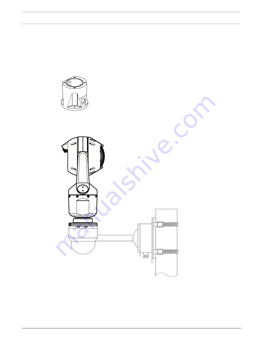
The hinged DCA is well-suited to installations on top of a pole.

Figure 8.3: Typical hinged DCA mount configuration

The camera can also be mounted on the side of a lamp post, pole, or similar column using the
Pole Mount Bracket (MIC-PMB). Be aware that lamp posts can often be subject to movement
and are not suitable platforms in all conditions or for all applications.

The figure below identifies the three mounting brackets (each sold separately) that are
necessary to mount the MIC camera on the side of a pole.

Note

: The figure identifies the part numbers, as well as the codes for the available colors (-BD

for black, WD for white, and GD for grey) of each mounting bracket.

Summary of Contents for MIC-7130-PB4

Page 1: ...MIC IP starlight 7000 HD MIC 7130 PB4 MIC 7130 PW4 MIC 7130 PG4 MIC 7230 B5 MIC 7230 W5 MIC 7230 G5 en Operation Manual ...

Page 2: ......

Page 3: ...rview of Mounting Options 22 9 Install the Camera 25 10 Make Connections Power and Control 26 10 1 About Camera Power and Control 26 10 2 Power Source Options 26 10 3 Ethernet Connections 27 10 4 Camera Connections 28 10 5 Connect the Camera to the Network 29 11 Cant the Camera 30 12 Typical System Configurations 36 12 1 Typical IP Configuration with 95 W midspan no I O connections 36 12 2 Typical...

Page 4: ...g 68 17 1 Storage Management 68 17 1 1 Device manager 68 17 1 2 Recording media 68 17 1 3 Activating and configuring storage media 68 17 1 4 Formatting storage media 69 17 1 5 Deactivating storage media 69 17 2 Recording Profiles 69 17 3 Maximum Retention Time 71 17 4 Recording Scheduler 71 17 5 Recording Status 72 18 Alarm 73 18 1 Alarm Connections 73 18 2 VCA 75 18 3 Virtual Masks 79 18 4 Audio ...

Page 5: ...etwork status 97 22 2 Playback 98 22 2 1 Selecting the recording stream 98 22 2 2 Searching for recorded video 98 22 2 3 Exporting recorded video 98 22 2 4 Controlling playback 98 23 Operation 99 23 1 Using Intelligent Tracking 99 23 2 Recommended Use of Your MIC Camera 102 23 3 Using the Wiper Washer Bosch Protocol 103 23 4 Using the Wiper Washer Pelco Protocol 104 23 5 Configuring Settings for I...

Page 6: ...ht All rights reserved Trademarks All hardware and software product names used in this document are likely to be registered trademarks and must be treated accordingly 1 3 Safety Precautions In this manual the following symbols and notations are used to draw attention to special situations Danger High risk This symbol indicates an imminently hazardous situation such as Dangerous Voltage inside the ...

Page 7: ...amera unit Doing so will invalidate the warranty Use common sense safety precautions especially in situations where there could be risk of injury if any part of the assembly becomes detached and falls Bosch recommends using the hinged DCA which allows installers to hang the MIC camera temporarily on the DCA to make electrical connections before bolting the camera to the DCA Ensure that the unit ca...

Page 8: ...rds Fuse rating For security protection of the device the branch circuit protection must be secured with a maximum fuse rating of 16A This must be in accordance with NEC800 CEC Section 60 Grounding Connect outdoor equipment to the unit s inputs only after this unit has had its ground terminal connected properly to a ground source Disconnect the unit s input connectors from outdoor equipment before...

Page 9: ...hese limits are designed to provide reasonable protection against harmful interference when the equipment is operated in a commercial environment This equipment generates uses and radiates radio frequency energy and if not installed and used in accordance with the instruction manual may cause harmful interference to radio communications Operation of this equipment in a residential area is likely t...

Page 10: ... signaling aspects of this product UL has only tested fire shock and or casualty hazards as outlined in Standard s for Safety for Information Technology Equipment UL 60950 1 UL Certification does not cover the performance or reliability of the security or signaling aspects of this product UL MAKES NO REPRESENTATIONS WARRANTIES OR CERTIFICATIONS WHATSOEVER REGARDING THE PERFORMANCE OR RELIABILITY O...

Page 11: ...k Group Regarding the Cornea Lens infrared hazard of this product the Exposure Hazard Value EHV at a test distance of 200mm is 2 19 based on EXEMPT Group exposure limits The EHV based on Risk Group 1 limits is 0 386 The HD for the Exempt Group is 297 mm Regarding the Retinal Blue Light hazard the EHV is 22 9 based on the EXEMPT Group exposure limits and a test distance of 200 mm The EHV based on R...

Page 12: ...ort Telephone 800 326 1450 Fax 585 223 3508 or 717 735 6560 Email technical support us bosch com Repair Center Telephone 585 421 4220 Fax 585 223 9180 or 717 735 6561 Email security repair us bosch com Canada Telephone 514 738 2434 Fax 514 738 8480 Europe Middle East Africa Region Please contact your local distributor or Bosch sales office Use this link http www boschsecurity com startpage html eu...

Page 13: ...re lifting or moving MIC7000 cameras because of their weight 6 7 kg 14 7 lb 2 1 Parts List Camera One 1 MIC IP starlight 7000 HD Camera One 1 Quick Installation Guide One 1 spanner tool to remove and to attach the yoke caps in order to cant the camera if desired and to remove the access plug from the camera head when installing the optional illuminator accessory sold separately One 1 base gasket O...

Page 14: ...g table identifies the optional accessories for MIC cameras Refer to the datasheets of each accessory for details Some accessories may not be available in all regions Accessories Description Accessories Description MIC DCA H MIC DCA HB MIC DCA HW MIC DCA HG Hinged Deep Conduit Adapter in Black White Grey MIC SCA MIC SCA BD MIC SCA WD MIC SCA GD Shallow Conduit Adapter in Black White Grey MIC CMB M...

Page 15: ...nshield Configure settings Refer to Section 13 Alarm Washer Interface Unit VIDEOJET connect PSU Cant the camera Refer to Section 11 Install cabling between power source and camera mounting site Install MIC Camera Refer to Section 9 Power supply source or PoE device Connect and configure camera in box or on table top stand Refer to Sections 5 6 Install optional accessories Refer to individual insta...

Page 16: ...16 en Overview of Installation Steps MIC IP starlight 7000 HD 2016 07 5 0 F 01U 291 520 Operation Manual Bosch Security Systems IPHelper http downloadstore boschsecurity com ...

Page 17: ...section of the box 2 Supply power to the camera and Connect the Camera to the Network page 29 Note that the wiper moves one time across the camera window and then returns to parked position 3 Configure the camera Refer to Configuration page 39 for details Note Do not change the camera orientation to Inverted while the camera is still in the box The camera head must be free to rotate If you must ch...

Page 18: ...ce the camera upright on a flat horizontal surface 3 Remove the foam covering the head of the camera 4 Supply power to the camera and Connect the Camera to the Network page 29 Note that the wiper moves one time across the camera window and then returns to parked position 5 Configure the camera Refer to Configuration page 39 for details Notice If you change the camera orientation to Inverted from t...

Page 19: ...s may occur then Bosch recommends installing a separate lightning conductor within 0 5 m 1 6 ft of the camera and at least 1 5 m 4 9 ft higher than the camera A good earth bonding connection to the camera housing itself will provide protection against damage from secondary strikes The camera housing itself is constructed to cope with secondary strikes If the correct lightning protection is applied...

Page 20: ...e incorrect mounting orientations of MIC cameras Correct mounting orientation upright inverted Correct mounting orientation canted Incorrect mounting orientation Note the position of the visor when the camera is installed in inverted orientation The visor is close to the top of the pan shaft the body of the MIC instead of at the bottom of the inverted camera Note For canted cameras ensure that you...

Page 21: ... HD Mounting Location and Mounting Orientation en 21 Bosch Security Systems Operation Manual 2016 07 5 0 F 01U 291 520 55 55 90 90 A u t o P i v o t Figure 7 2 MIC7000 Tilt Range 145 each direction 290 if AutoPivot enabled ...

Page 22: ...pment such as power supplies The hinged DCA is well suited to installations on top of a pole Figure 8 3 Typical hinged DCA mount configuration The camera can also be mounted on the side of a lamp post pole or similar column using the Pole Mount Bracket MIC PMB Be aware that lamp posts can often be subject to movement and are not suitable platforms in all conditions or for all applications The figu...

Page 23: ...Typical Pole mount configuration Other locations for mounting the camera include the top of a building the side wall of a building the corner of a building and under the eave of a building MIC SPR BD WD GD MIC SCA BD WD GD MIC WMB BD WD MG Figure 8 5 Typical Wall mount configuration MIC CMB BD WD MG MIC SCA BD WD GD MIC WMB BD WD MG Figure 8 6 Typical Corner mount configuration ...

Page 24: ...gure 8 7 Direct surface mount camera upright MIC base gasket Figure 8 8 Direct surface mount camera inverted MIC base gasket IP67 Weatherization Connector Kit Notice Observe all appropriate safety precautions and local building regulations Refer to the MIC Series Mounting Brackets Installation Guide for installation instructions ...

Page 25: ...roper installation Caution ELECTRIC SHOCK HAZARD To reduce the risk of electric shock disconnect power to the camera and or to the power supply unit before moving the camera before installing any accessories and before mounting the camera You can install the camera onto a MIC DCA or a MIC wall mount or directly to a mounting surface using the MIC7000 IP67 Connector Kit MICIP67 5pk sold separately ...

Page 26: ...t6e cable connection is required to view to power and to control the camera The camera can also accept a standard 24 VAC power source if a High PoE network interface will not be used User supplied wiring must be in compliance with electrical codes Class 2 power levels For maximum reliability the camera can be connected simultaneously to a High PoE Midspan and a separate 24 VAC power source If High...

Page 27: ...t Connections Caution Ethernet cables must be routed through earth grounded conduit capable of withstanding the outdoor environment Note Consult the National Electrical Code NEC for cable bundling requirements and limitations Cable Type Cat5e Cat6e Ethernet directly to the camera or to a network switch between the camera and the network Maximum Distance 100 m 330 ft Bandwidth 10BASE T 100BASE TX a...

Page 28: ...wires 24 gage to VG4 A PSU1 or VG4 A PSU2 if not using a PoE network Line L Black Neutral N White 3 Chassis Earth ground wire 18 gage with connector lug Green 4 RS 485 connections for communication to from the MIC ALM WAS 24 Purple Yellow GND Brown 5 Liquid tight cordgrip in the base of the camera 6 RJ45 coupler female to female Note If the MIC camera will be installed directly to a mounting surfa...

Page 29: ...S 485 wires to the MIC ALM WAS 24 optional 5 Attach the green ground wire item 3 in the figure above from the camera to an earth ground connection on the mounting surface using the supplied screw or a suitable user supplied fastener Option B 1 Connect an Ethernet crossover cable from the RJ45 connector of the camera directly to a networking device such as a computer a DVR NVR etc 2 Attach the gree...

Page 30: ...ed so that it doesn t tilt downward unexpectedly after the Torx screws are removed from the yoke arms and pinch fingers or other body parts Notice Risk of damage to the camera Do not under any circumstances cant the camera while the camera is on its side Cant the camera from an upright position only in order to prevent screws or other objects from falling into the open spaces in the arms when the ...

Page 31: ...anual 2016 07 5 0 F 01U 291 520 1 Remove the yoke cap item 3 in the figure below on one yoke arm of the camera using a torque wrench with in drive item 1 user supplied and the supplied spanner tool item 2 Repeat for the second arm 1 4 Figure 11 12 Remove yoke caps with spanner tool ...

Page 32: ...rx head screws to 5 mm Hex head screws Both head types accommodate a T30 Torx bit Be sure to note which screw head type is on your MIC 7000 camera since there are different torque requirements as shown in Torque requirements for yoke arm screws page 34 Figure 11 13 Remove screws from yoke arms Notice Risk of damage to the device Carefully support the head of the camera while completing the next fo...

Page 33: ...6 07 5 0 F 01U 291 520 5 Carefully rotate the arms and head assembly forward Notice Risk of damage to the device Do not cant the camera or let it fall in the wrong direction The camera should cant only in the direction indicated in the figure directly below Figure 11 14 Cant the camera head ...

Page 34: ...einsert yoke arm screws ABCD 7 Using a torque wrench user supplied tighten the screws to the proper torque using the sequence described in the table below 8 Recheck all four screws to ensure the proper torque value Torque requirements for yoke arm screws T30 T27 Torx SN xxxxxxx46028xxxxxx Dec 2014 5 mm Hex T30 Torx SN xxxxxxx46029xxxxxx Dec 2014 7 5 N m 5 5 ft lb C D A B 7 5 N m 5 5 ft lb 15 N m 1...

Page 35: ...era en 35 Bosch Security Systems Operation Manual 2016 07 5 0 F 01U 291 520 9 Attach the yoke caps using a torque wrench with in drive and the supplied spanner tool 1 4 N m 12 in lb 1 4 Figure 11 16 Attach yoke caps 10 Canting is complete ...

Page 36: ...re 12 17 Typical IP configuration with 95 W midspan no I O connections 1 MIC7000 camera 2 MIC Hinged DCA MIC DCA Hx 3 High PoE Network cable Cat5e Cat6e user supplied between camera and 95 W midspan NPD 9501A 4 95 W midspan NPD 9501A 5 Data only IP cable Cat5e Cat6e user supplied between midspan and head end network Note The total length of Cat5e Cat6 cable must be less than 100 m 328 ft between t...

Page 37: ...WAS 24 1 MIC7000 camera 6 24 VAC Power pack 1A 50 60 Hz user supplied 2 MIC Hinged DCA MIC DCA Hx 7 Washer pump accessory 3 RS 485 cable 3 conductor user supplied 8 Interface cable for washer control user supplied 4 MIC ALM WAS 24 enclosure 9 Alarm input output interface cables user supplied 5 Interface cable for 24 VAC user supplied for MIC ALM WAS 24 10 Monitored Normally Open switch for Supervi...

Page 38: ...e port labeled PoE on VIDEOJET connect 7000 2 Data only IP cable Cat5e Cat6e to the head end network Note The cable to the head end also can be fiber optic cable from one of the two SFP slots 3 Alarm input output interface cables user supplied 4 Alarm output cables user supplied 5 120 230 VAC 50 60 Hz 6 Audio input interface cable user supplied 7 External washer pump user supplied 8 Washer output ...

Page 39: ...notes on using Microsoft Internet Explorer in the online Help in Internet Explorer If you choose to use a computer running Microsoft Internet Explorer or any of the Bosch software the computer must conform to the following minimum requirements Operating System Windows XP Service Pack 3 or Windows 7 32 or 64 bits Processor Intel Pentium Quad Core 3 0 GHz or comparable RAM 2048 MB Free Hard Disk Spa...

Page 40: ...camera images from a Web browser To change the IP address or any network settings you can use the Configuration Manager software or the MIC7000 Series server 13 2 1 Using the Configuration Manager Configuration Manager is an optional network utility provided on the Bosch Security Systems Web site Use the Configuration Manager Manual to make any configuration changes Note Depending on the PC networ...

Page 41: ...the Set button for a change to take effect Notice Save each change with the associated Set button Clicking the Set button saves the settings only in the current field Changes in any other fields are ignored Some changes only take effect after the unit is rebooted In this case the Set button changes to Set and Reboot 1 Make the desired changes 2 Click the Set and Reboot button The camera reboots an...

Page 42: ...lose Camera ID Each device should be assigned a unique identifier that can be entered here as an additional means of identification Initiator extension Add text to an initiator name to make identification easier in large iSCSI systems This text is added to the initiator name separated from it by a full stop You can see the initiator name in the System Overview page 14 2 User Management A password ...

Page 43: ...y possible to identify and correctly evaluate simultaneous recordings when all units are operating on the same time 1 Enter the current date Since the unit time is controlled by the internal clock there is no need to enter the day of the week it is added automatically 2 Enter the current time or click the Sync to PC button to copy your computer s system time to the camera Note It is important that...

Page 44: ...lications and subsequent function extensions Select Time server for a time server that works with the protocol RFC 868 14 4 Display Stamping Various overlays or stamps in the video image provide important supplementary information These overlays can be enabled individually and are arranged on the image in a clear manner After you set all necessary parameters click the View Control link to see how ...

Page 45: ...uously display sector or shot title overlays in the image Select Momentary to display sector or shot title overlays for a few seconds OSD titles can be displayed at a position of your choice or it can be set to Off for no overlay information 1 Select the desired option from the list 2 Specify the exact position Position XY 3 In the Position XY fields enter the values for the desired position Camer...

Page 46: ...ters on this page in accordance with the GB T 28181 national standard H 264 elementary stream Select this checkbox to select or to enable the H 264 elementary stream Registration timeout Enter a value in milliseconds for the registration timeout The default is 3600 Heartbeat timeout Enter the value in seconds for the heartbeat timeout The default is 15 Server ID Enter the ID of the server Server I...

Page 47: ...in the local network or at an Internet address Device logo Enter the path to a suitable graphic if you want to replace the product name The image file can be stored on a local computer in the local network or at an Internet address Notice If you want to use the original graphics again simply delete the entries in the Company logo and Device logo fields Show VCA metadata When video content analysis...

Page 48: ...when the field Application variant in Installer Menu page 50 is set to either of the following values camera name IO for a camera connected to a MIC Alarm Washer Interface unit MIC ALM WAS 24 camera name VJC 7000 for a camera connected to a VIDEOJET connect 7000 unit VJC 7000 90 Show alarm outputs Alarm outputs are shown next to the video image as icons along with their assigned names If the alarm...

Page 49: ...ing feature Show Special Functions Here you can specify whether the LIVE page displays the Special Functions section Path for JPEG and video files 1 Enter the path for the storage location of individual images and video sequences that you can save from the LIVE page 2 If necessary click Browse to find a suitable directory Video file format Select a file format for the live page display The MP4 for...

Page 50: ...n the field Base frame rate requires approximately 10 20 seconds to complete During this time no changes can be made The cameo image freezes The orientation of the camera Options Normal Inverted Canted SC settings Click the Default button to restore all camera settings to their original defaults Reboot device Click the Reboot button to reboot the camera There is a ten 10 second pause before the ca...

Page 51: ...ream 1 is transmitted for alarm connections and automatic connections Notice All parameters combine to make up a profile and are dependent on one another If you enter a setting that is outside the permitted range for a particular parameter the nearest permitted value will be substituted when the settings are saved Profile name Profile number Default Profile name Description Profile 1 HD Image Opti...

Page 52: ...fps appears next to the text field or slider Video resolution Select the desired resolution for the video image Expert settings If necessary use the expert settings to adapt the I frame quality and the P frame quality to specific requirements The setting is based on the H 264 quantization parameter QP GOP structure Select the structure that you require for the group of pictures depending on whethe...

Page 53: ... the value for I P frame delta QP to the lowest possible value This is how to save bandwidth and memory in normal scenes The image quality is retained even in the case of increased movement since the bandwidth is then filled up to the value that is entered under Maximum bit rate Background delta QP Select the appropriate encoding quality level for a background region defined in Encoder Regions The...

Page 54: ...ing profile Select one of the following profiles for each stream Profile number Default Profile name Description Profile 1 HD Image Optimized For an HD image the video bit rate and frame quality are adjusted to ensure that the picture quality is the priority Profile 2 HD Balanced For an HD image the video bit rate and frame quality are adjusted to a median profile for everyday use Profile 3 HD Bit...

Page 55: ...ty and therefore have a decreased encoding quality Eight encoder regions can be defined To define encoder regions follow these steps 1 From the first drop down box the unlabeled Regions selection list select one of the eight available regions The drop down box has the default option of Region 1 2 Click the box to add an area 3 Use the mouse to define the area shape that the region covers and to po...

Page 56: ...mask outline to less than half of the default size 7 Click the Enabled check box to activate the privacy mask 8 Move the privacy mask if desired Place the cursor inside the privacy mask area in the preview window and then click and drag to move the privacy mask Note Keep it as close to the center of the Preview Window as possible 9 Click SET to save the size and the position of the privacy mask 10...

Page 57: ...d saves the color settings Extended ATW default allows the camera to constantly adjust for optimal color reproduction Manual Red and Blue gain can be manually set to a desired position Sodium Lamp Auto Automatically adjusts for sodium vapor light to restore objects to their original color Sodium Lamp Optimizes the sodium vapor light to restore objects to their original color Red Gain The red gain ...

Page 58: ...ct this option the camera disables Shutter automatically Shutter Adjusts the electronic shutter speed AES Controls the time period for which light is gathered by the collecting device The default setting is 1 60 second for NTSC and 1 50 for PAL cameras The range of settings is from 1 1 to 1 10000 Maximum automatic exposure This limits the integration time when Frame Integration is active The defau...

Page 59: ...Select a value between 10 and 55 in increments of 5 default 30 The lower the value the earlier the camera will switch to color mode Night mode priority Select the option to which the camera should give priority while in night mode Motion Color default Night mode shutter Controls the time period for which light is gathered by the collecting device while in night mode Values are 1 8 1 15 and 1 30 th...

Page 60: ...n 1 and 15 Maximum zoom speed Controls the zoom speed Zoom limit Select the appropriate limit for zooming the camera 20x 30x Digital zoom Digital zoom is a method of decreasing narrowing the apparent angle of view of a digital video image It is accomplished electronically without any adjustment of the camera s optics and no optical resolution is gained in the process Select Standard default to ena...

Page 61: ...ed number of seconds Settings range from 5 to 120 The default is 30 Auto pan left limit Sets the left Auto Pan limit of the camera Use the preview window to move the camera to the left pan limit and click the button The camera will not move past this limit when in Auto Pan Between Limits mode AUX 2 ON Auto pan right limit Sets the right Auto Pan limit of the camera Use the preview window to move t...

Page 62: ...ve the camera to that position 2 Select the radio button On for the parameter Compass 3 Click the button next to North point to set the calibration point North point Click the Set button to overwrite the existing North point A dialog box appears with the message Overwrite North point To confirm click OK To cancel click Cancel Click the Clear button to reset the North point to factory defaults A di...

Page 63: ...the appropriate action Show or Set Preposition Enter the number of the preposition to map Function Select the appropriate function from the drop down list Function Description Start auto pan Start auto pan with limit Stop auto pan Start custom tour Stop custom tour Start tour Stop tour Start playback A Stop playback A Start playback B Stop playback B Compass on Compass off Azimuth on Azimuth off S...

Page 64: ...le light inhibit off Auto tracker on Auto tracker off Privacy mask on Privacy mask off Acknowledge alarms Wiper continuous Wiper intermittent Wiper on shot Wiper off 16 11 Sectors Sector The camera s pan capability is 360 and is divided into 16 equal sectors This section allows you to apply a title for each sector and to designate any sectors as a Blanked Sector To define a title for sectors 1 Pla...

Page 65: ...ols IR illuminators When ON the camera gives a much better image at low light levels Options are On Off Auto IR intensity Select the percentage of intensity of the infrared IR light No white light Select On to disable the white light illuminators The options in the field White light illuminators are disabled Select Off to enable white light illuminators White light illuminators Select On to turn o...

Page 66: ...Pixel Counter The number of horizontal and vertical pixels covered by the highlighted area is displayed below the picture With these values you can check whether the requirements for specific functions for example identification tasks are fulfilled 1 Click Freeze to freeze the camera image if the object that you want to measure is moving 2 To reposition a zone place the cursor over the zone hold d...

Page 67: ...y Systems Operation Manual 2016 07 5 0 F 01U 291 520 AUX Command BLC AGC Night mode Night mode auto Alarm output 1 Alarm output 2 Alarm output 3 Alarm output 4 White light Intelligent defog Intelligent tracking Serial mode Select Simplex or Full duplex ...

Page 68: ...onfiguration parameters The storage system selected must be available on the network and completely set up It must have an IP address and be divided into logical drives LUNs 1 Enter the IP address of the required iSCSI destination in the iSCSI IP address field 2 If the iSCSI destination is password protected enter the password into the Password field 3 Click Read The connection to the IP address i...

Page 69: ...d storage media list to select it 2 Click Remove below the list The storage medium is deactivated and removed from the list 17 2 Recording Profiles A recording profile contains the characteristics of the tracks that are used for recording These characteristics can be defined for ten different profiles The profiles can then be assigned to days or times of day on the Recording Scheduler page Each pr...

Page 70: ...elect the stream to be used for standard recordings Stream 1 Stream 2 I frames only Alarm recording Pre alarm time You can select the required pre alarm time from the list field Post alarm time You can select the required post alarm time from the list field Alarm stream Select the stream to be used for alarm recordings Stream 1 Stream 2 I frames only Encoding interval and bit rates from profile Se...

Page 71: ...e cursor over all the periods to be assigned to the selected profile 3 Use the right mouse button to deselect any of the intervals 4 Click the Select All button to link all time intervals to the selected profile 5 Click the Clear All button to deselect all of the intervals 6 When you are finished click the Set button to save the settings in the unit Holidays You can define holidays that are not in...

Page 72: ...cannot be modified You can stop the recording activity at any time and modify the settings 1 Click the Start button to activate the recording scheduler 2 Click the Stop button to deactivate the recording scheduler Running recordings are interrupted and the configuration can be changed Recording status The graphic indicates the recording activity of the camera You will see an animated graphic while...

Page 73: ...g IP address for the desired remote station Destination password If the remote station is password protected enter the password here In this page you can save a maximum of ten destination IP addresses and hence up to ten passwords for connecting to remote stations If connections to more than ten remote stations are to be possible for example when initiating connections via higher ranking systems s...

Page 74: ...t a particular video output and a split image is set for this output on the receiver you can also select from Decoder the decoder in the receiver that is to be used to display the alarm image Notice Refer to the destination unit documentation concerning image display options and available video outputs Decoder Select a decoder of the receiver to display the alarm image The decoder selected has an ...

Page 75: ... can be useful if you want to test a number of different configurations Save a functioning configuration and test new settings You can use the saved configuration to restore the original settings at any time Notice If computing power becomes short the highest priority is always the live images and recordings This can lead to impairment of the video content analysis You should therefore observe the...

Page 76: ...s here directly You can find information on this in the relevant documents on the product CD supplied Metadata is always created for a video content analysis unless this was explicitly excluded Depending on the analysis type selected and the relevant configuration additional information overlays the video image in the preview window next to the parameter settings Options are MOTION IVA 5 6 IVA 5 6...

Page 77: ... to continuous movement by a tree in the wind etc the relevant fields can be deactivated 4 Click Select Area to configure the sensor fields A new window will open 1 If necessary click Clear All first to clear the current selection fields marked yellow 2 Left click the fields to be activated Activated fields are marked yellow 3 If necessary click Select All to select the entire video frame for moni...

Page 78: ... tampering associated with EMC interference noisy scene as the result of a strong interference signal in the vicinity of the video lines as an example should trigger an alarm Reference Check You can save a reference image that is continuously compared with the current video image If the current video image in the marked areas differs from the reference image an alarm is triggered This allows you t...

Page 79: ...This allows users to mask background motion in the scene such as moving trees pulsating lights busy roads etc To create a virtual mask 1 Select the number of the Virtual mask In the video preview window a dark grey rectangle appears with the text Mask x where x is the number of the mask 2 Select the mask with your mouse Move the mouse to position the mask over the area of the view that you want to...

Page 80: ...sly defined e mail address Send alarm e mail Select On if you want the unit to automatically send an alarm e mail in the event of an alarm Mail server IP address Enter the IP address of a mail server that operates on the SMTP standard Simple Mail Transfer Protocol Outgoing e mails are sent to the mail server via the address you entered Otherwise leave the box blank 0 0 0 0 SMTP user name Enter a r...

Page 81: ...n the Alarm Task Editor field or change existing scripts in line with your requirements 3 When you are finished click the Set button to transmit the scripts to the unit If the transfer was successful the message Script successfully parsed is displayed over the text field If it was not successful an error message will be displayed with further information 18 7 Alarm Rules An alarm rule can define w...

Page 82: ...ng of the device is opened 4 Choose one of the following output commands for both Output 1 and Output 2 settings Note Not all options are available for all cameras None no defined command Alarm Output defines a physical connection from the open collector alarm output AUX On defines a standard or custom keyboard ON command AUX Off defines a standard or custom keyboard OFF command Scene defines a pr...

Page 83: ...ilter option for quick search in recordings Enter a unique and clear name here Caution Do not use any special characters for example in the name Special characters are not supported by the system s internal management 19 2 Alarm Outputs Idle state Select Open if you want the relay to operate as an NO contact or select Closed if the relay is to operate as an NC contact Operating mode Select an oper...

Page 84: ...nt subnet enter the IP address of the gateway here Otherwise leave the box blank 0 0 0 0 Caution If you change the IP address subnet mask or gateway address the camera is only available under the new addresses after the reboot IPv6 Consult with the network administrator before making changes to this section IP address Enter the desired IP address for the camera in this field The IP address must be...

Page 85: ...ocol You may have to activate this protocol via your browser configuration You must also activate the protocol for the Java applications via the Java control panel in the Windows control panel Notice If you want to allow only secure connections with SSL encryption you must select the Off option for each of the parameters HTTP browser port RCP port 1756 and Telnet support This deactivates all unsec...

Page 86: ...must have registered the required host name for the unit on that site Notice Information about the service registration process and available host names can be found at DynDNS org Provider The value in this field defaults to dyndns org Select another option as necessary Host name Enter the host name registered on DynDNS org for the camera here User name Enter the user name you registered at DynDNS...

Page 87: ...transportation management applications and transportation equipment such that they interoperate with each other Select a port for NTCIP and the Address from the appropriate drop down lists Note The NTCIP section appears only for cameras with an NTCIP license TCP port The device can receive data from an external TCP sender for example an ATM or POS device and store it as metadata Select the port fo...

Page 88: ...ity of the different data channels can be set by defining the DiffServ Code Point DSCP Enter a number between 0 and 252 as a multiple of four For alarm video you can set a higher priority than for regular video and you can define a Post Alarm Time over which this priority is maintained 20 5 Multicast In addition to a 1 1 connection between an encoder and a single receiver unicast the camera can en...

Page 89: ...the port address of the required stream here Streaming Click the checkbox to activate multicast streaming mode for the relevant stream An enabled stream is indicated by a check mark Multicast packet TTL You can enter a value to specify how long the multicast data packets are active on the network This value must be greater than one if multicast is to be run via a router 20 6 Image Posting You can ...

Page 90: ...es Options are JPEG default YUV420 TIFF Target Select the target the name of the account on the server to which to save images Timeout s Enter the number of seconds after which image posting will time out The default is 0 no timeout Maximum image width px Enter a number for the maximum width in pixels for the saved images For automatic width selection use value 0 20 7 Accounts Four separate accoun...

Page 91: ... 0 F 01U 291 520 20 8 IPv4 Filter Use this setting to configure a filter that allows or blocks network traffic that matches a specified address or protocol IP Address 1 2 Enter the IPv4 address that you want to allow or block Mask 1 2 Enter the subnet mask for the appropriate IPv4 address ...

Page 92: ...he device no longer being addressable requiring it to be replaced Progress The progress bar displays the progress of the firmware upload Note Once the progress bar reaches 100 a reset page may appear If this page appears allow the reset page to complete its action Upload history Click Show to view the firmware upload history Configuration Click Choose File to navigate to the required firmware file...

Page 93: ...e plus sign To delete a certificate click the trashcan icon to the right of the certificate Note You can delete only certificates that you have added you cannot delete the default certificate File list Add a certificate file to the file list 1 Click Add The Add certificate window appears 2 Click Choose File to navigate to the required file 3 Click Upload Delete a certificate from the file list Cli...

Page 94: ...n Service MIC IP starlight 7000 HD 2016 07 5 0 F 01U 291 520 Operation Manual Bosch Security Systems Select the text on this page with a mouse and copy it so that it can be pasted into an e mail if required ...

Page 95: ...ons page 22 1 1 Prepositions The camera displays Preposition 1 through Preposition 6 Select the appropriate preposition to view the video image for that preposition scene In the lower left of the video image the OSD displays the Camera number title the Preposition Scene number and the Preposition Scene number stored Below the list of prepositions scenes is a drop down list showing the stored prepo...

Page 96: ... control in the View Control tab Tour A Tour B Click one of these buttons to start the continuous playback of a recorded guard tour A recorded tour saves all manual camera movements made during the recording including its rate of pan tilt and zoom speeds and other lens setting changes To stop a tour click a directional control in the View Control tab Focus Click this button to activate the Auto Fo...

Page 97: ...w 22 1 9 Audio communication Audio can be sent and received via the Live page if the unit and the computer support audio 1 Press and hold the F12 key on the keyboard to send an audio signal to the unit 2 Release the key to stop sending audio All connected users receive audio signals sent from the unit but only the user who first pressed the F12 key can send audio signals others must wait for the f...

Page 98: ...original or a condensed speed 4 In the Location drop down box select a target 5 Click Export to save the video track Note The target server address is set on the Network Accounts page 22 2 4 Controlling playback The time bar below the video image allows quick orientation The time interval associated with the sequence is displayed in the bar in gray Arrows indicate the position of the image current...

Page 99: ...re controls the pan tilt zoom actions of the camera to keep the selected object in the scene 12 ft 3 66 m 6 ft 1 83 m 8 ft 2 44 m H D To activate the Intelligent Tracking feature one of the following conditions must be met The Silent IVA option must be selected in the VCA page on the Settings tab Refer to VCA page 75 IVA must be active for at least one preset scene in the VCA page on the Settings ...

Page 100: ...t Tracking operation Avoid motion from moving leaves branches that present a persistent fixed motion Operation of Intelligent Tracking The Intelligent Tracking feature behaves in one of the following ways Camera detects an object in motion and automatically tracks the object User actions always take precedence over Intelligent Tracking If the camera is actively tracking an object and a user takes ...

Page 101: ...ene for IVA alarms or IVA rule violations If an IVA rule is violated it triggers the advanced tracking feature of the camera to start following the object person that triggered the alarm This allows the camera to track moving objects of interest without getting distracted by other moving objects in the scene To activate this mode you must enable IVA by selecting either IVA number or IVA number Flo...

Page 102: ...tween a desired set of presets For best results always ensure that each preset has a dwell time of at least 5 seconds 2 Scene Illumination and Focus Settings Your camera uses a high sensitivity image sensor and a high quality lens with a precise drive train control to maintain the best focus of the image The Autofocus mechanism tries continuously to make the image details appear sharp Under low li...

Page 103: ...and wipes five times 3 The washer turns off The wiper turns off 4 The camera returns to its previous PTZ position and to inactive mode if applicable To activate the wiper manually or if the corresponding alarm was activated or deactivated Press ON 102 ENTER Note The wiper will turn off automatically after 5 minutes of use To activate intermittent wipe Press ON 103 ENTER The wiper wipes twice then ...

Page 104: ...you already have a preset stored at that position the system prompts you to overwrite the current scene 4 Activate the wash wiper function Press 1 and then press AUX ON on the keyboard The camera moves to preset 62 The nozzle sprays cleaner onto the camera window and then the wiper wipes the window The camera then returns to where it was positioned previously or it continues to perform the tour th...

Page 105: ... enters Night Mode with Aux 57 or alarms Use this for manual control of Night Mode Model MIC camera without IR Setting Auto On When using external IR lamps user must control the IR Focus Correction using Aux 67 or alarms For control of IR Focus Correction with a MIC camera non IR There are no other valid combinations Any other combination can cause the camera to have problems focusing focus issues...

Page 106: ...General Select Identification 2 Delete all of the text in the field Camera name 3 Rename the camera if desired 4 Click Set to save 23 7 Two line and Three line Camera Titles There are two options to display camera titles but these should not be used together Choose one of the following modes Mode 1 Azimuth Elevation Compass Zoom Options Mode 2 Camera Title combined with Compass Mode 1 Azimuth Elev...

Page 107: ...OKING X or LOOKING XX without quotation marks where X or XX is the compass direction This line cannot be edited by the end user LOOKING will always appear in English and will be at a fixed location on the OSD The X or XX designates the compass direction that updates automatically as the camera pans A identifies North South East or West AA identifies Northeast Northwest Southeast or Southwest Three...

Page 108: ...ection 21 to 65 NE Northeast 66 to 110 E East 111 to 155 SE Southeast 156 to 200 S South 201 to 245 SW Southwest 246 to 290 W West 291 to 335 NW Northwest 336 to 20 N North 21 to 65 NE Northeast 66 to 110 E East 111 to 155 SE Southeast 156 to 200 S South 201 to 245 SW Southwest 246 to 290 W West 291 to 335 NW Northwest 336 to 20 N North The camera uses the Azimuth Zero point usually set to magneti...

Page 109: ... connections Ensure that the maximum distance between any two Ethernet connections is 100 m 328 ft or less If O K then If you are behind a firewall ensure that the Video Transmission mode is set to UDP Camera does not operate at all or does not operate as expected after being subjected to extreme low temperatures below 40 40 F Allow the camera to warm up The camera requires a 60 minute warm up pri...

Page 110: ...For IP enabled cameras Check to see if you have a web page If you do then try cycling the camera s power off and on If you do not then you may have the wrong IP address Use Configuration Manager to identify the correct IP address If O K then Check that there is 24 V output from the transformer If O K then Check the integrity of all wires and mating connectors to the camera Picture is dark Check th...

Page 111: ...k event Check the integrity of the mechanical parts and the screws especially on the yoke arms If there is obvious and severe damage stop using the camera and contact your Bosch Service Center for assistance If no damage is evident complete one of the following steps a Cycle the power on the camera b Send command AUX OFF 65 to remove the OSD message If IVA is configured on your camera the OSD mess...

Page 112: ...ge Inspection of this device shall only be carried out by suitably trained personnel in accordance with the applicable code of practice for example EN 60097 17 Information about cameras with illuminators The text in this section applies only to cameras which have the optional illuminator accessory When servicing the device disconnect power to the device to avoid possible exposure to the eyes If di...

Page 113: ... has been developed and manufactured using high quality materials and components that can be reused This symbol means that electronic and electrical devices that have reached the end of their working life must be disposed of separately from household waste In the EU separate collecting systems are already in place for used electrical and electronic products Please dispose of these devices at your ...

Page 114: ...HD 2016 07 5 0 F 01U 291 520 Operation Manual Bosch Security Systems 27 Technical data For product specifications see the datasheet for your camera available on the appropriate product pages of the Online Product Catalog at www boschsecurity com ...

Page 115: ... Level Adjust Enters the Iris Level Adjustment menu On Off 14 Set Autopan and Scan Speed Enters the speed adjustment slide bar On Off 15 Set Pre position Tour Period dwell Enters the dwell adjustment slide bar On Off 18 AutoPivot Enable Enables disables AutoPivot On Off 20 Backlight Comp Turns Backlight Compensation BLC on or off On Off 23 Electronic Shutter Enters the Shutter Speed slide bar On O...

Page 116: ...on screen display Off Disables on screen display On 61 OSD Display Adjust Adjust the view of the On screen Display On 62 Pre position Scene Title menu Enters the Pre position Title menu Refer to Specifying a Shot or a Sector Title On 63 Zone Sector Title Menu Enters the Zone Title menu Refer to Specifying a Shot or a Sector Title On 64 Alarm Status Enters the Alarm Status menu Off 65 Alarm Acknowl...

Page 117: ...on and off On Off 81 Alarm Output 1 Open Collector On Activates output Off Deactivates output On Off 82 Alarm Output 2 Open Collector On Activates output Off Deactivates output On Off 83 Alarm Output 3 Open Collector On Activates output Off Deactivates output On Off 84 Alarm Output 4 Relay On Activates output Off Deactivates output On Off 86 Sector Blanking Masking Enters exits the Sector Blanking...

Page 118: ...15 seconds This cycle repeats until turned OFF On Off 104 Wiper On Off On One shot wipes five times then turns off On Off 105 Wash Wipe On Off On Camera moves to designated washer preset 62 wiper washer automatically start On 149 Reset Position Correction Counters On Reset position correction counters On 606 Power Mode Temporarily displays current power mode 24 VAC POE POE or Unknown On Off 700 Pr...

Page 119: ...u Set 899 Reset ALL Restores all settings to original defaults and clears all user programmed settings except for custom camera titles Set 900 Edit Tour 1 Standard Enters the Standard Tour Scene menu Shot 900 Edit Tour 2 Custom Enters the Custom Tour Scene menu Set Shot 901 999 Adds Removes a Preposition Shot from Tour 1 Set Adds preset Shot Removes preset 28 2 Pelco Protocol Pelco P D PTZ Command...

Page 120: ...custom preset tour Tour 2 92 Preset Action Press and hold for2 seconds Sets the Left pan limit for an AutoScan with Limit Stops enabled 93 Preset Action Press and hold for 2 seconds Sets the Right pan limit for an AutoScan with Limit Stops enabled 95 Preset Action Press Enables or disables Limit Stops in the Setup Menu for AutoScan Action Press and hold for 2 seconds 96 Preset Action Press Stops a...

Page 121: ......

Page 122: ...Bosch Sicherheitssysteme GmbH Robert Bosch Ring 5 85630 Grasbrunn Germany www boschsecurity com Bosch Sicherheitssysteme GmbH 2016 Bosch Security Systems Inc 1706 Hempstead Road Lancaster PA 17601 USA ...

Reviews: