6720850722 (2015/06)
CS 200
14 | Service menu
7.4
Diagnosis
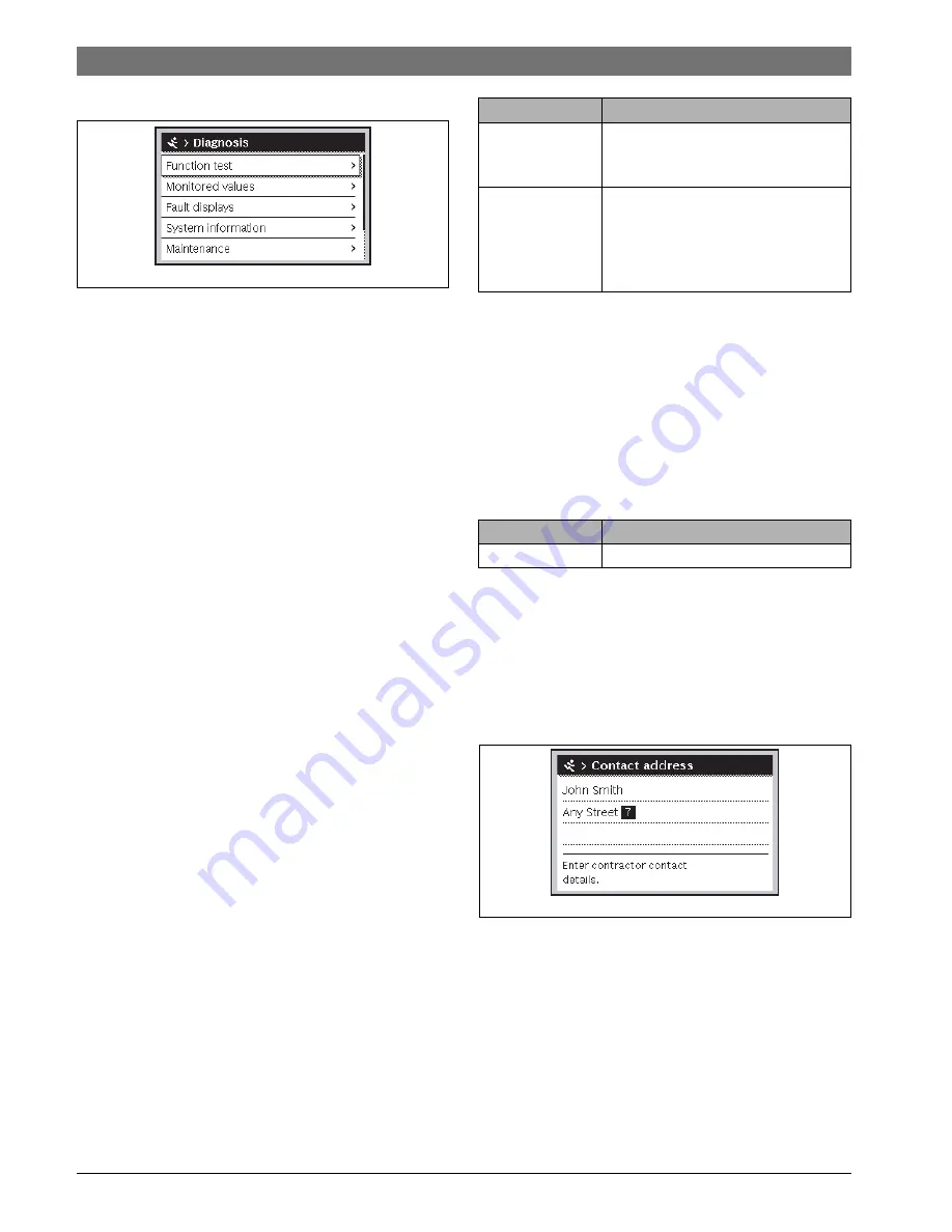
Fig. 9
Diagnosis menu
The
Diagnosis
service menu contains a number of tools for
diagnosis. Note that the menu items shown will vary depending
on the heating system.
7.4.1 Function tests
This menu can be used to test active system components
individually. If
Enable function tests
is set to
Yes
in this menu,
the normal heating operation is interrupted in the entire
system. All settings are saved. The settings in this menu are only
temporary and revert to the respective default settings as soon
as the
Enable function tests
is set to
No
or the
Function test
menu is closed. The available functions and the possible
settings vary depending on the system installed.
A function test is performed by setting the parameters of the
listed component accordingly. You can check whether the
mixer, pump or valve responds appropriately by inspecting the
behaviour of the corresponding component.
The
solar pump
can be tested, for instance:
•
Off
: The pump stops.
•
On
: The pump starts.
7.4.2 Monitored values
System settings and measurements are displayed in this menu.
For example, the system can display whether the maximum
collector temperature or the current cylinder temperature has
been reached.
You can also call up detailed information on system parts, e.g.
the swimming pool. The information and values that are
provided depend on the system that has been installed.
Observe the technical documentation for modules and other
system components.
7.4.3 Fault displays
The current faults and the fault history can be called up in this
menu.
Table 12 Information in the fault display menu
7.4.4 System information
The software versions of the BUS nodes installed in the system
can be called up in this menu.
7.4.5 Maintenance
You can add a contact address in this menu. When the solar
controller displays a fault code, the added address is also
displayed. The end customer can notify the installer to arrange
an appointment (
Chapter 9, page 15).
Table 13 Settings in the Maintenance menu
Contact address
The contact address is automatically displayed to the end user
in case of a fault.
Entering company name and telephone number
The current cursor position will flash (marked by
|
).
Fig. 10
Entering a contact address
▶ Turn the rotary control knob to move the cursor.
▶ Press the rotary control knob to activate the input field.
▶ Turn the rotary control knob to enter characters.
▶ Press the Back key when you have finished making entries.
▶ Press the Back key again to return to the next previous
menu.
0010003114.001
Menu item
Description
Active faults
All current faults that are present in the
system are displayed here according to
their severity.
Fault history
The last 20 faults are displayed here,
sorted in order of the time of occurrence.
The fault history can be deleted in the
Reset menu (
Chapter 7.4.6,
page 15).
Menu item
Description
Contact address
"Contact address"
0010003273.001
Summary of Contents for CS 200
Page 18: ......
Page 19: ......
Page 20: ...Bosch Thermotechnik GmbH Junkersstrasse 20 24 D 73249 Wernau www bosch thermotechnology com ...


